Hardware
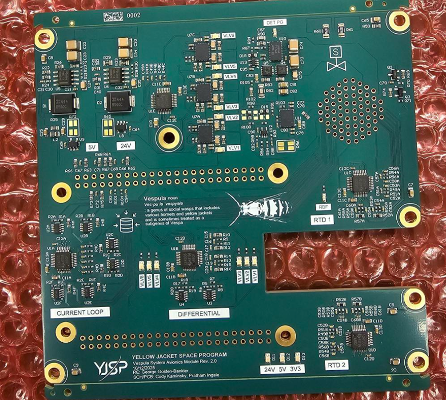
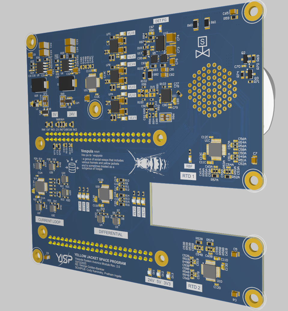
Assembled Flight SAM hardware
Clean photo of the corrected Rev 4 Flight SAM after the interface/routing revision.
Redesign and validation of a 48 V flight engine controller for valve actuation, ignition, and sensor acquisition
Revision Responsible Engineer
Look through the copper layers and routing.
Spin around the board model in 3D.
The reasoning, bring-up, bugs, and test results behind the board.
Project overview
48 V
Vehicle Bus
15+
Pins Remapped
~22 mA target
Protected Sensors
6 layers
Stackup
A six-layer flight engine controller on the 48 V avionics bus. I inherited this board rather than designing it from scratch, and my revision work focused on the broken interfaces: BeagleBone pin mapping, connector/control/ADC-related routing, bring-up, integration, and validation.
This page sticks to the work I actually owned on Rev 4: pin remapping, interface/routing changes, bring-up, integration, and validation. The power, igniter, and ADC circuits themselves were inherited.
Hardware & test evidence
Hardware
Clean photo of the corrected Rev 4 Flight SAM after the interface/routing revision.
PCB Layout
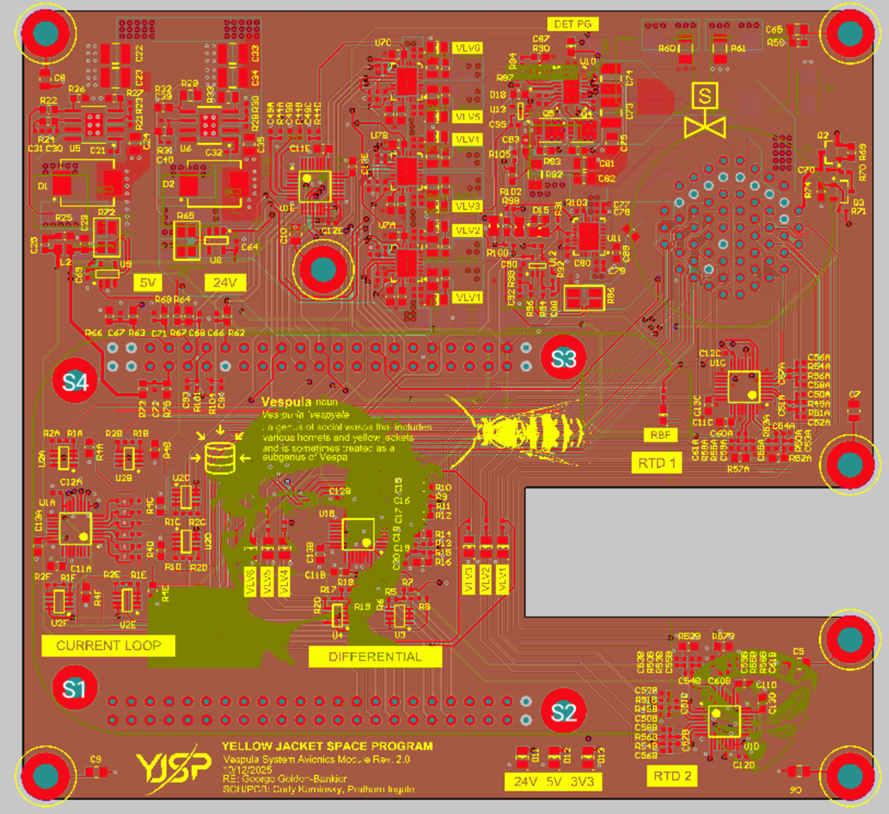
Full-board Altium view of Rev 4, including the BeagleBone, connector, and ADC-related routing changes I made.
Integration
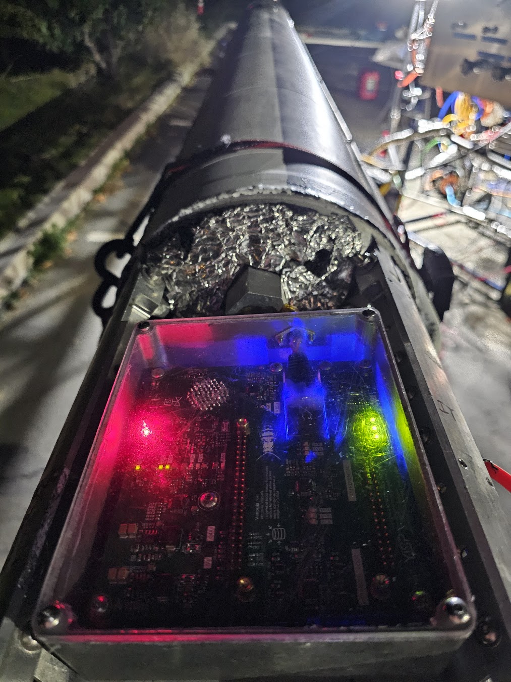
Rev 4 powered up in the real propulsion-avionics stack during integration.
Sensors
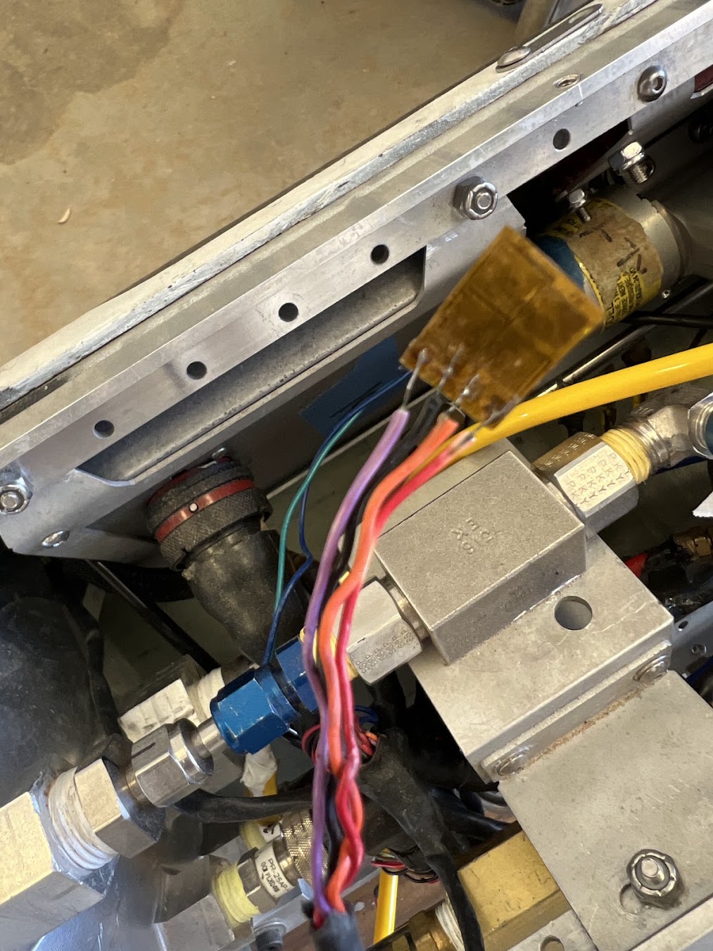
One of the representative propulsion-sensor installations connected through the Flight SAM.
PCB
Altium 3D view of the revised Flight SAM, useful for seeing connector placement and the physical board organization around the interface changes.
Test history
Verify that the revised controller boots reliably, acquires valid sensor data, and drives engine-control outputs predictably.
Inherited design
Designed
Audit identified pin-mapping, boot-state, ADC-polarity, and power-converter issues that prevented reliable operation.
Corrected revision
Validated
Electrical and PCB changes were brought up through staged subsystem testing and returned the controller to operational use.
Design deep dives
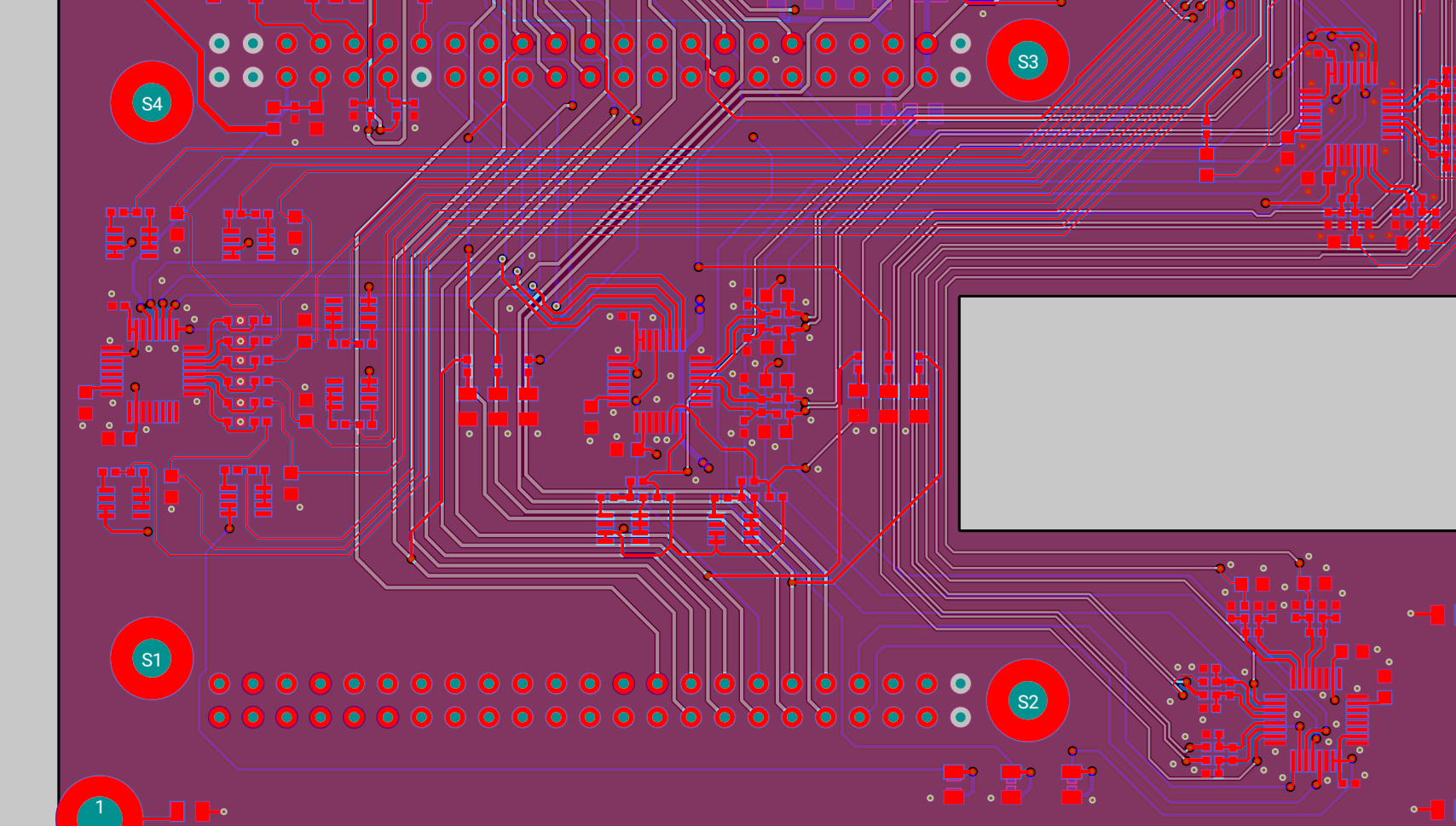
Revision
48 V BusHow I audited the inherited pin map and interfaces, figured out which assumptions disagreed across hardware/firmware, and carried the fixes into the PCB.
Power
Valves / IgnitersHow I validated the inherited valve and igniter paths after the revision without claiming the original actuation/power design as mine.
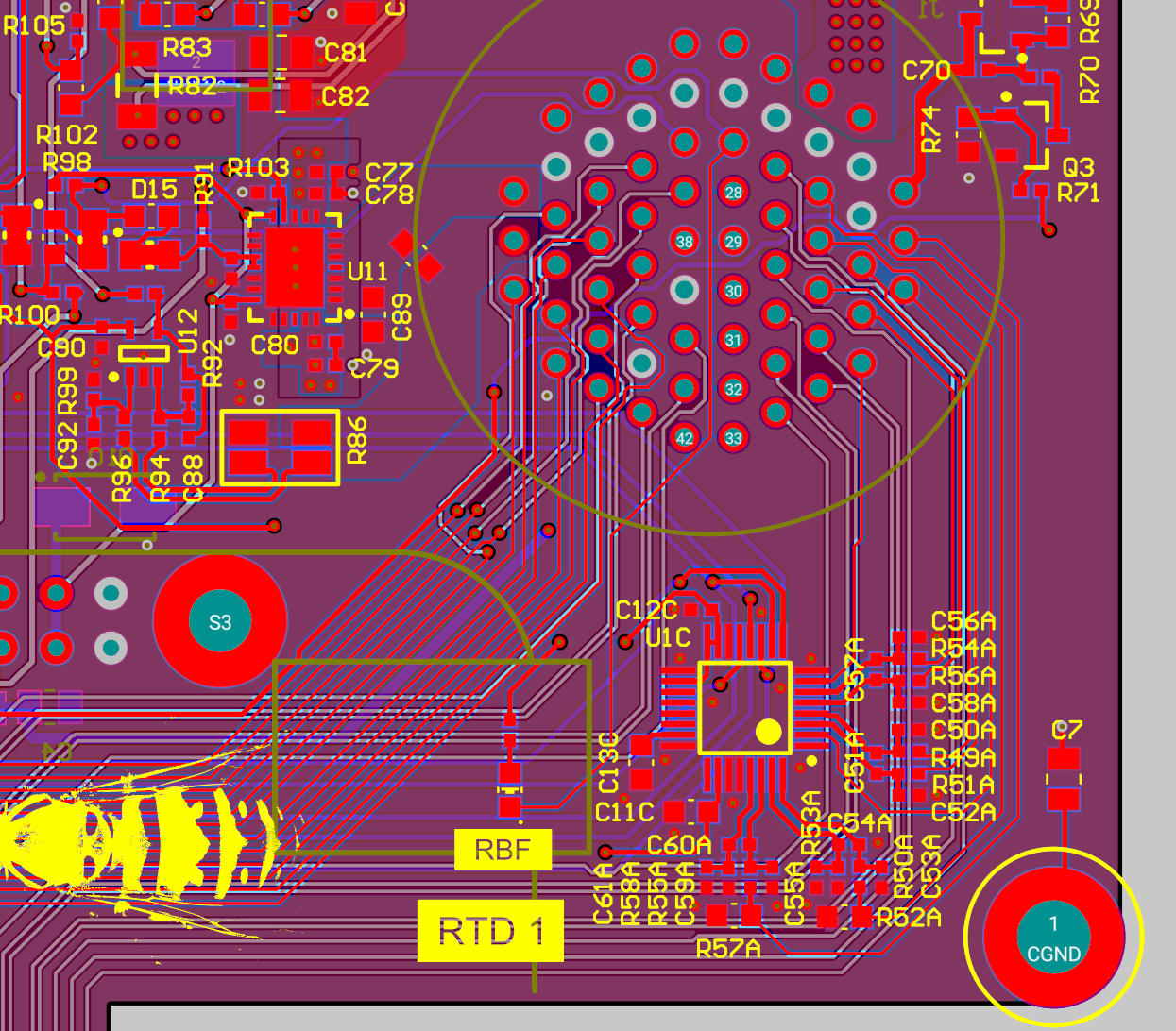
Sensors
RTD / PTHow I fixed ADC-related mapping/routing issues and then checked that the sensor paths still behaved correctly in the integrated system.