Vespula Avionics Module Engineering Notes
Purpose
The Vespula Avionics Module is the flight engine controller. It runs from the 48 V avionics bus, drives valves and igniters, and reads RTDs, pressure transducers, and differential sensors during engine start and shutdown.
My Responsibility
I was the Revision Responsible Engineer. This was not a clean-sheet board for me—I inherited the first revision and focused on the pieces that were actually broken at the interfaces: BeagleBone pin ownership, connector mapping, routing, bring-up, and integration.
The underlying power, igniter, and ADC circuits were inherited. My design work was mainly the pin reassignment and the PCB changes needed to make those interfaces agree with the processor and firmware.
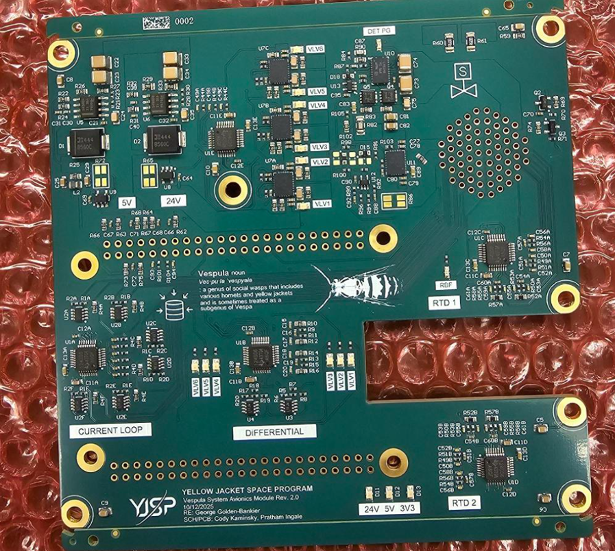
What Was Wrong
The first revision had a few problems that made the board hard to bring up reliably:
- boot-sensitive BeagleBone pins were being driven into bad states;
- more than 15 BeagleBone control/interface pins needed to move;
- several ADC paths had polarity or mapping issues;
- the igniter power stage was not regulating reliably;
- actuation and sensing could not be checked consistently in the original setup.
The annoying part was that these issues crossed schematic, firmware, and PCB boundaries. Fixing a pin in only one place was not enough.
Revision Strategy
I rebuilt the signal ownership from the controller and vehicle connectors inward. Boot-sensitive pins got moved, ADC-related mapping/polarity issues got corrected, and the BeagleBone pin map was brought back in line with what the engine-control software actually expected.
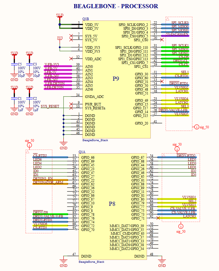
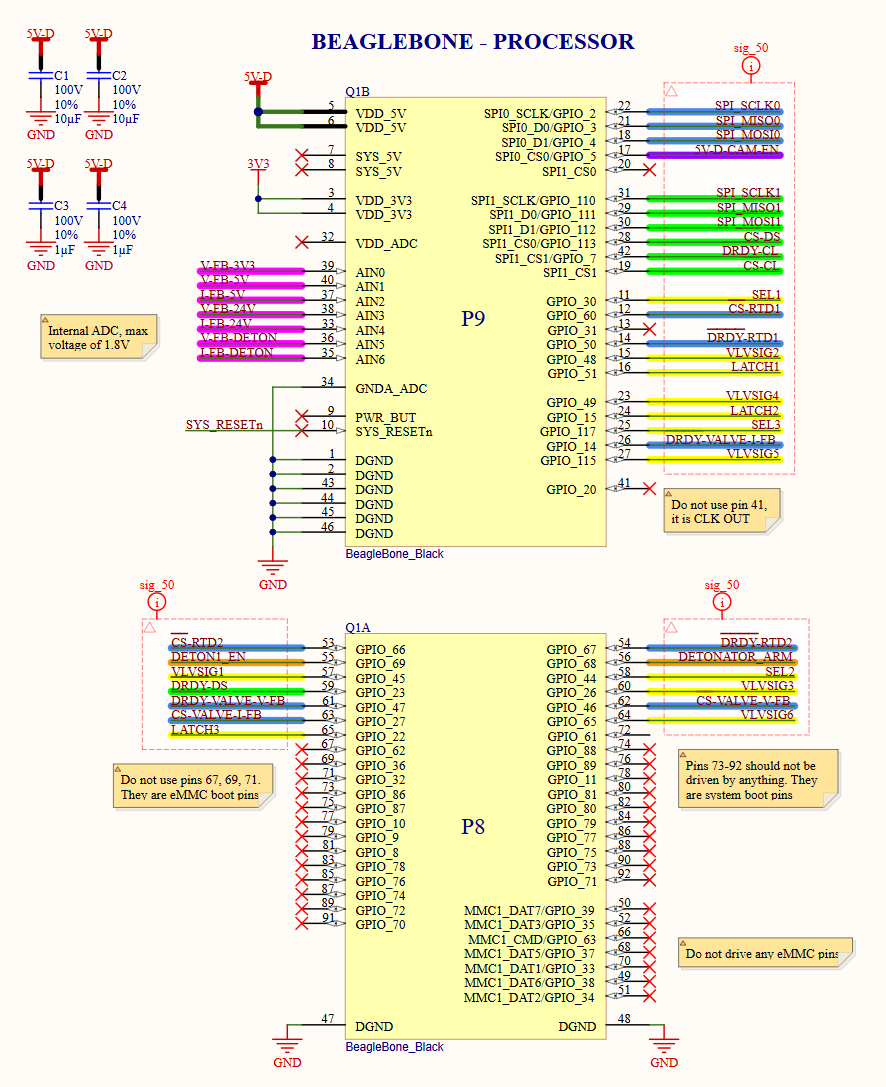
My PCB work was then mostly about carrying those interface fixes through the board: rerouting the BeagleBone signals, updating connector paths, and cleaning up the ADC-related routing without pretending I designed the inherited analog front ends.
PCB Layout
The six-layer layout keeps the valve/igniter current paths away from the lower-level sensor routing as much as practical. There is a dedicated power layer and adjacent references for the controller and sensor signals.
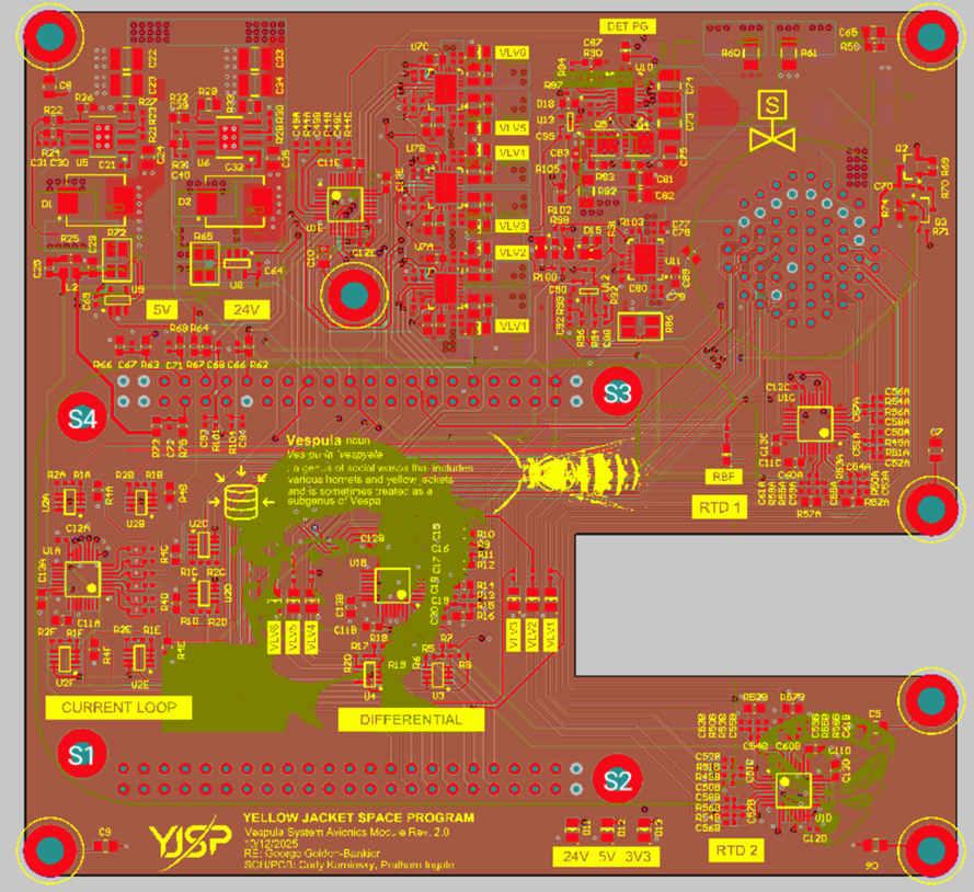
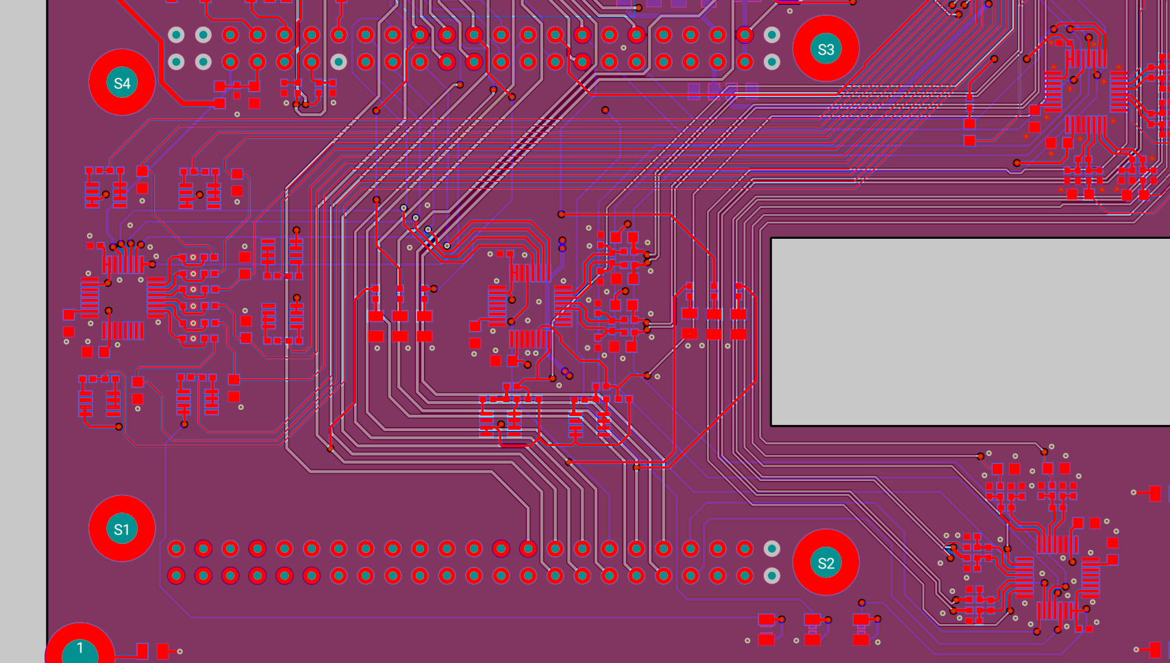
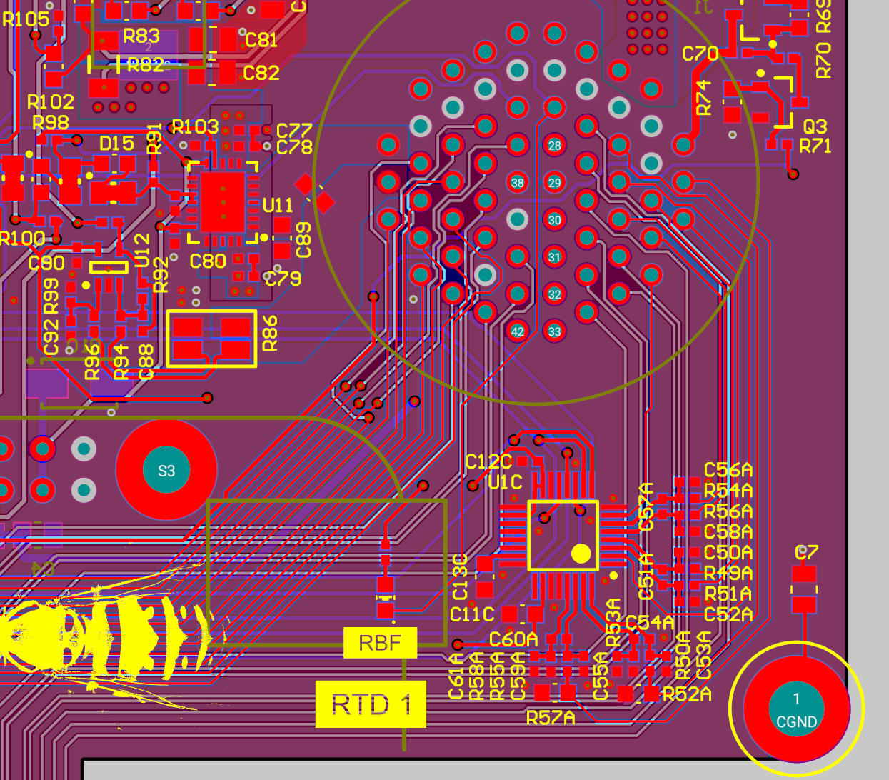
The board is easier to think about as a few physical regions instead of one giant routing problem:
- igniter current path;
- solenoid-driver area;
- converter section;
- sensor acquisition;
- BeagleBone interface;
- vehicle connector boundary.
Bring-Up
I started with controller boot and regulated rails, then moved into ADC polarity, sensor scaling, valve outputs, and igniter operation.
The big milestone was not just “it powers on.” The revised board booted reliably, read sensors correctly, and behaved repeatably with the real propulsion hardware connected.
What I Took Away
The useful lesson here was how to audit an inherited board without getting lost in individual symptoms. I had to trace each signal from schematic intent, through the processor pin, through the PCB, into firmware, and finally onto the bench.
Next Revision
I would add better converter-loop test access, make the boot-sensitive signals more obvious on the schematic, and keep one shared pin-ownership table between electrical and firmware.