Revision Architecture
The Vespula Flight SAM was very much not a clean-sheet project for me. I inherited a board with the 48 V bus, BeagleBone, propulsion sensing, valves, ignition, and Ethernet already in place, but a bunch of the interface assumptions disagreed with the processor, firmware, or PCB.
My job was basically to make all of those assumptions line up well enough that the board could boot, be debugged, and actually be trusted on the vehicle.
What The Audit Found
This was not a cleanup-for-cleanup's-sake revision. The things I found were real bring-up problems:
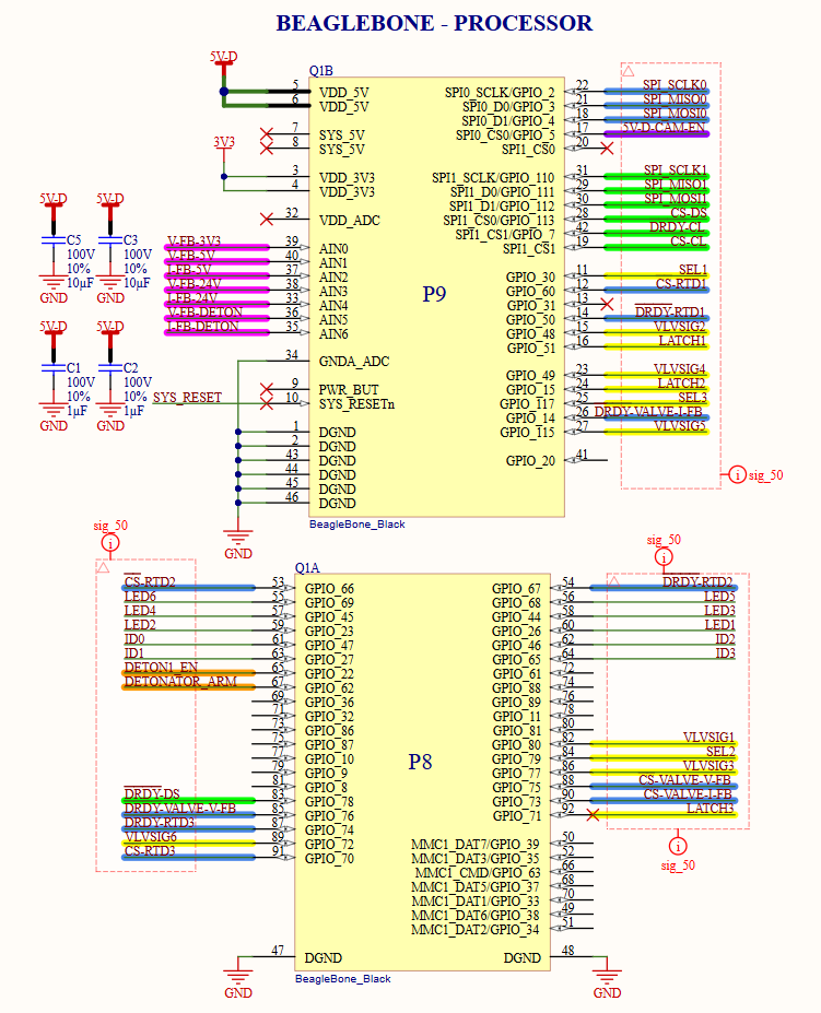
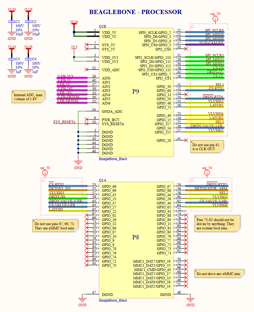
- boot-sensitive BeagleBone pins were being driven into invalid states;
- more than 15 BeagleBone control/interface pins required reassignment;
- several ADC paths had incorrect polarity or channel mapping;
- igniter-power regulation was not stable/repeatable;
- actuation and sensing behavior could not be validated consistently in the inherited configuration.
The annoying part was that none of these lived in one file. Moving a pin touched firmware and routing, an ADC polarity fix touched both the schematic and software scaling, and the power issue crossed component values and the PCB.
Rebuilding Signal Ownership
I audited the controller from the outside in:
- vehicle connector and harness signals;
- BeagleBone physical pins and boot behavior;
- SPI/GPIO ownership;
- ADC channel/polarity mapping;
- valve/igniter command paths;
- regulated power domains;
- the corresponding PCB routes.
That process exposed cases where the schematic label was internally consistent but disagreed with what the processor or firmware expected.
Six-Layer Revision
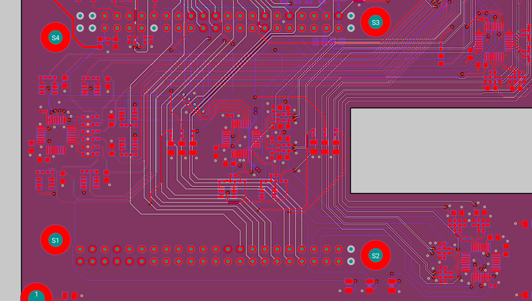
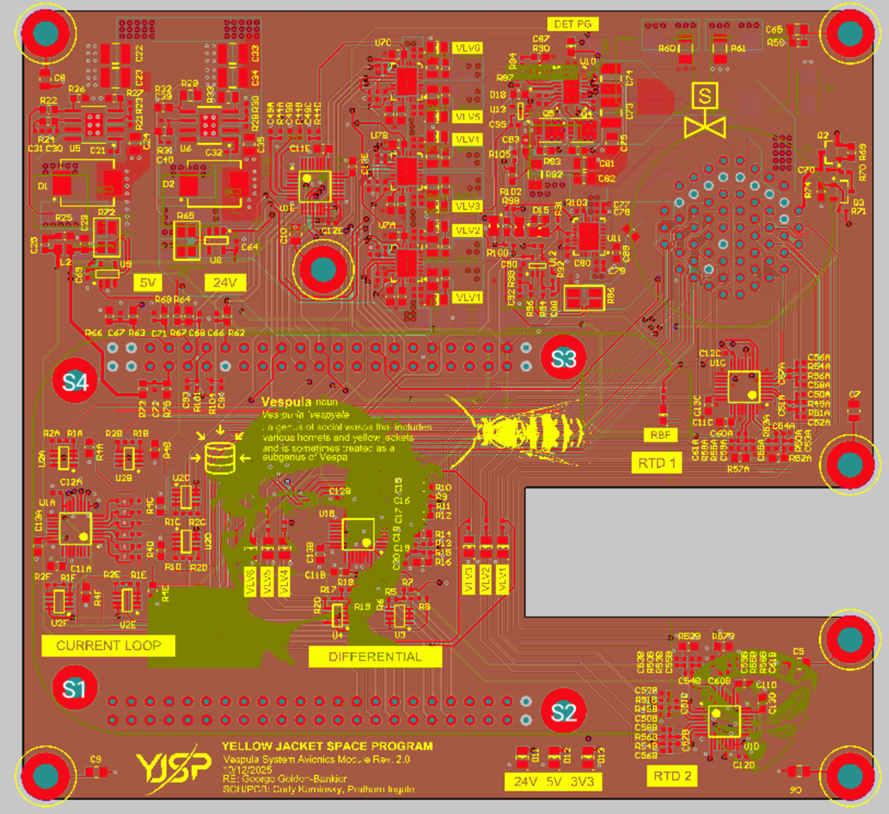
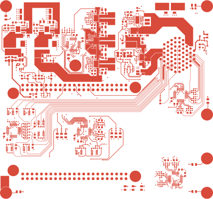
The corrected board uses a six-layer structure:
- L1 — signal/components
- L2 — ground
- L3 — signal
- L4 — power
- L5 — ground
- L6 — signal/components
The layer structure let the new routing preserve continuous references while separating high-current actuation/converter regions from the low-level sensor and controller interfaces.
Bring-Up
I brought the corrected revision up in stages:
- dead-board and controller boot checks;
- 48 V-derived regulated rails;
- ADC polarity/channel verification;
- sensor scaling and acquisition;
- valve output and feedback;
- igniter power/operation;
- Ethernet and integrated Flight Computer operation.
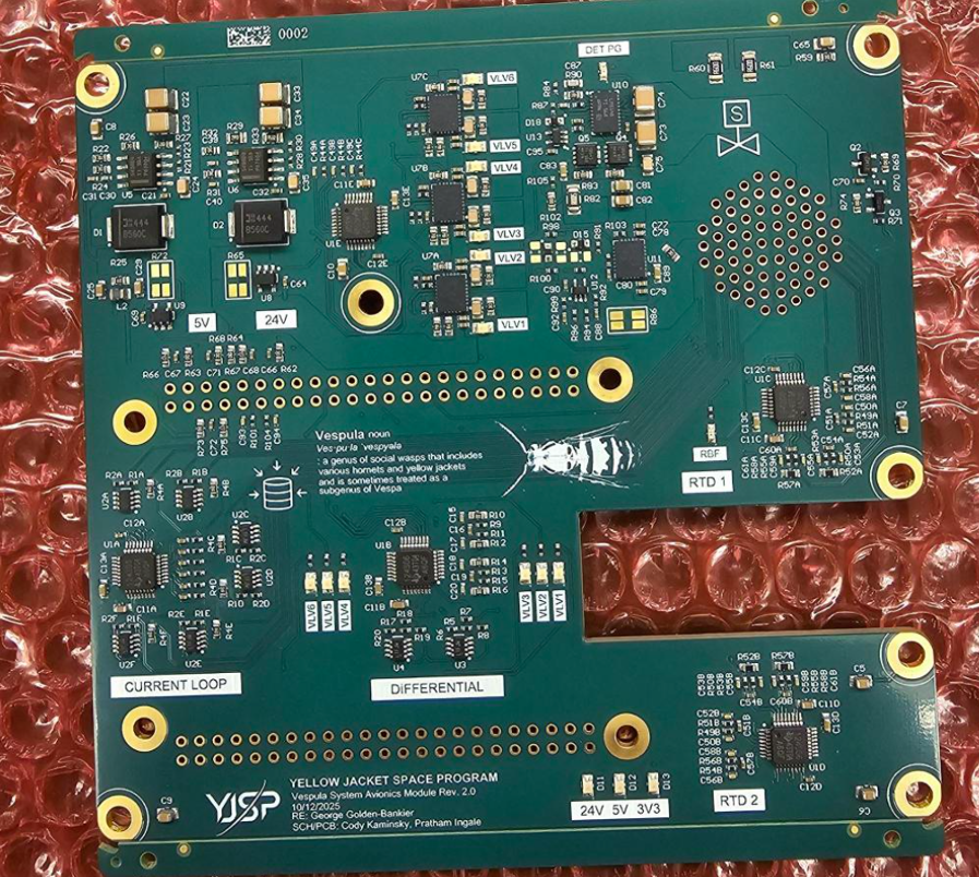
The win was not just “the board turns on now.” Rev 4 booted reliably, read the sensors correctly, and behaved repeatably with the actual propulsion hardware connected.
Result
This project was mostly about the boundaries people tend to underestimate: boot rules, pin ownership, analog polarity, power behavior, PCB routing, and firmware all had to agree before the board became boring enough to use.