Actuation and Ignition
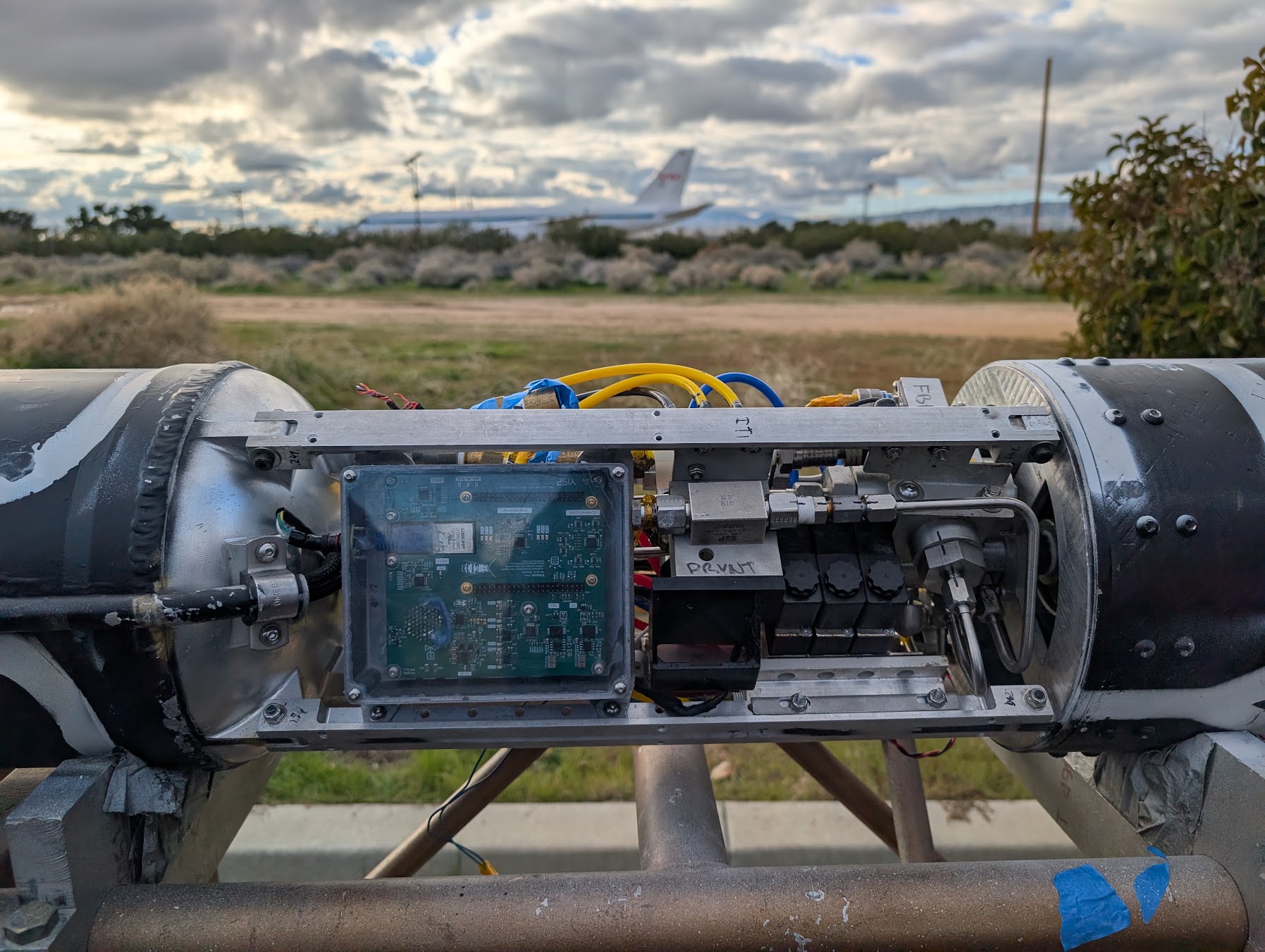
The Flight SAM is where a software command turns into something physical on the propulsion system. It has to switch real valve/igniter loads from the 48 V environment while still giving us enough feedback to tell the difference between off, disconnected, on, and actually broken.
Power Path
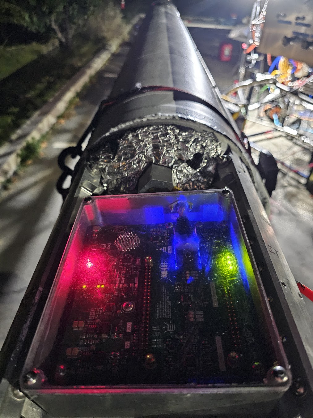
The board receives the vehicle's 48 V avionics bus and generates local 24 V and 5 V rails for actuation, compute, and measurement functions.
The high-current regions are intentionally separated from RTD, pressure-transducer, differential-sensor, and ADC circuitry. On a mixed-signal engine controller, the return path is just as important as the outgoing valve current: actuation current should not become part of the analog measurement reference.
Valve Channels
I did not want to call a valve channel 'validated' just because the GPIO toggled. I checked the electrical states we actually care about:
- connected and off;
- disconnected;
- connected and on;
- shorted/faulted.
That required checking the switched output together with valve-current and valve-voltage feedback, using the actual solenoid load rather than assuming a bench resistor represented every operating condition.
Igniter Power Problem
The inherited revision also had unstable igniter-power behavior. That could not be treated as a firmware issue because the instability existed in the local power stage itself.
The revision changed the converter/compensation implementation, and then I brought it back up the same way as everything else: rail first, command path second, real output last.
Layout Boundary
The layout separates:
- converter switching loops;
- solenoid/igniter current paths;
- output connectors;
- controller GPIO/control signals;
- sensor acquisition and ADC references.
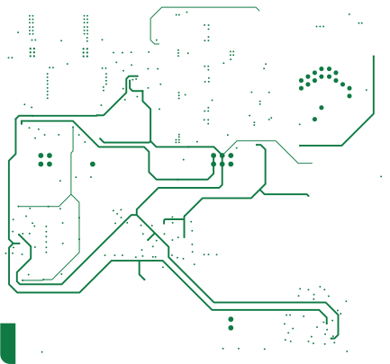
This separation prevents the fastest/highest-current loops from sharing unnecessary impedance with the lowest-level measurement paths.
Validation
The actuation side was brought up after the controller and sensor interfaces were already known-good. That sequencing made it possible to distinguish a bad command, bad feedback signal, bad power stage, or actual load fault without debugging all four at once.
By the end of bring-up, the valve and igniter behavior was repeatable enough that the board could be treated like actual propulsion hardware instead of a science project on the bench.