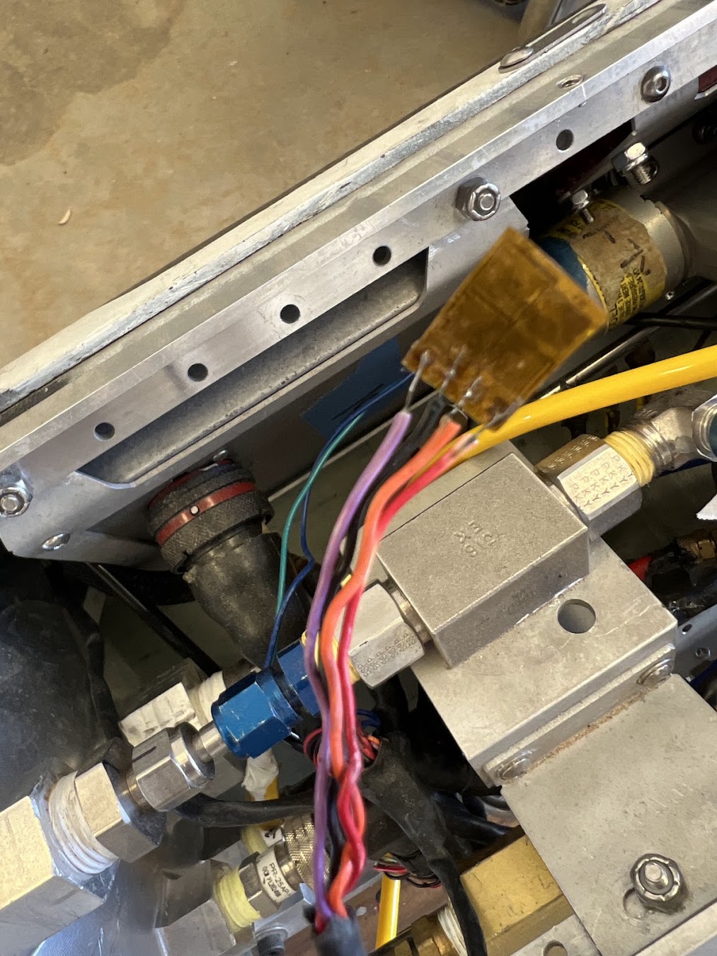
Sensor Layout and Validation
The Flight SAM has to do two pretty different jobs at once: drive propulsion hardware and act like a DAQ. So the sensor side still has to behave while converters, valves, igniters, Ethernet, and a Linux module are all sitting on the same PCB.
Measurement Groups
The Vespula implementation supports multiple external ADC groups for:
- 4–20 mA pressure transducers;
- valve current;
- valve voltage;
- board/power voltage;
- board/power current;
- thermocouples;
- differential sensors;
- RTDs.
The external ADCs use SPI with separate chip-select/data-ready mappings for the different measurement groups.
What The Revision Fixed
The inherited board contained ADC polarity/mapping inconsistencies. One of the easy traps here is thinking 'SPI works' means the sensor path works. A channel can talk perfectly over SPI and still be the wrong channel or the wrong polarity.
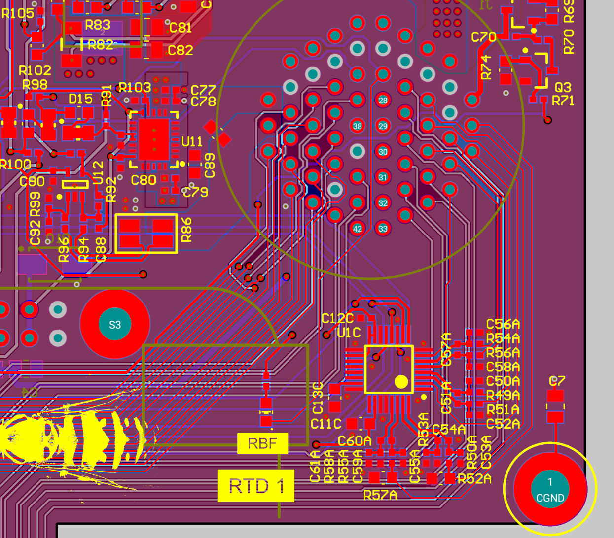
I audited the path all the way through:
sensor connector → analog front end → ADC input → SPI channel → BeagleBone pin → software mapping
That prevented a “working SPI bus” from being mistaken for a validated sensor interface.
Sensor Protection
The historical validation procedure explicitly checks protected external sensor channels around a 22 mA current-limit target.
The protection serves two purposes: a failed external sensor/harness should not turn into an uncontrolled load on the SAM, and one sensor fault should remain localized enough that the rest of the acquisition system stays observable.
PCB Separation
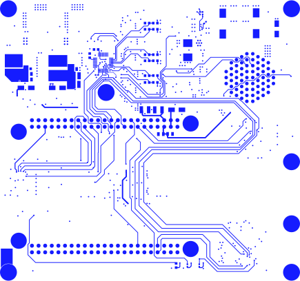
The six-layer layout keeps sensor routing and ADC regions away from the converter/actuation loops where practical, while the two ground-reference layers provide continuous return paths.
Validation Sequence
The measurement side was verified in increasing system depth:
- confirm ADC communication/register access;
- confirm channel identity and polarity;
- apply known electrical stimulus;
- verify scaling/plausibility;
- test protected channels near their intended current-limit behavior;
- repeat with actual vehicle sensors;
- operate while actuation hardware is active.
That last step is the one I care about most. A sensor channel is not really proven if it only looks good on a quiet bench while every noisy output on the board is turned off.