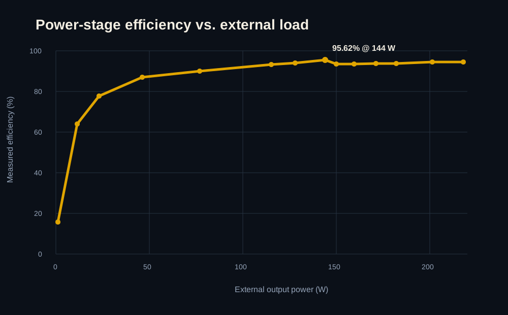
Measured
Power-stage efficiency sweep
Measured 24 V efficiency during Rev 5 bring-up; the sweep peaked at 95.62% at 144 W external load.
Fault-tolerant recovery avionics with triple-MCU voting and ten high-current deployment channels
Design Responsible Engineer
Browse the exported schematic and design sheets.
Look through the copper layers and routing.
Spin around the board model in 3D.
The reasoning, bring-up, bugs, and test results behind the board.
Project overview
10
Deployment Channels
3
Independent MCU Domains
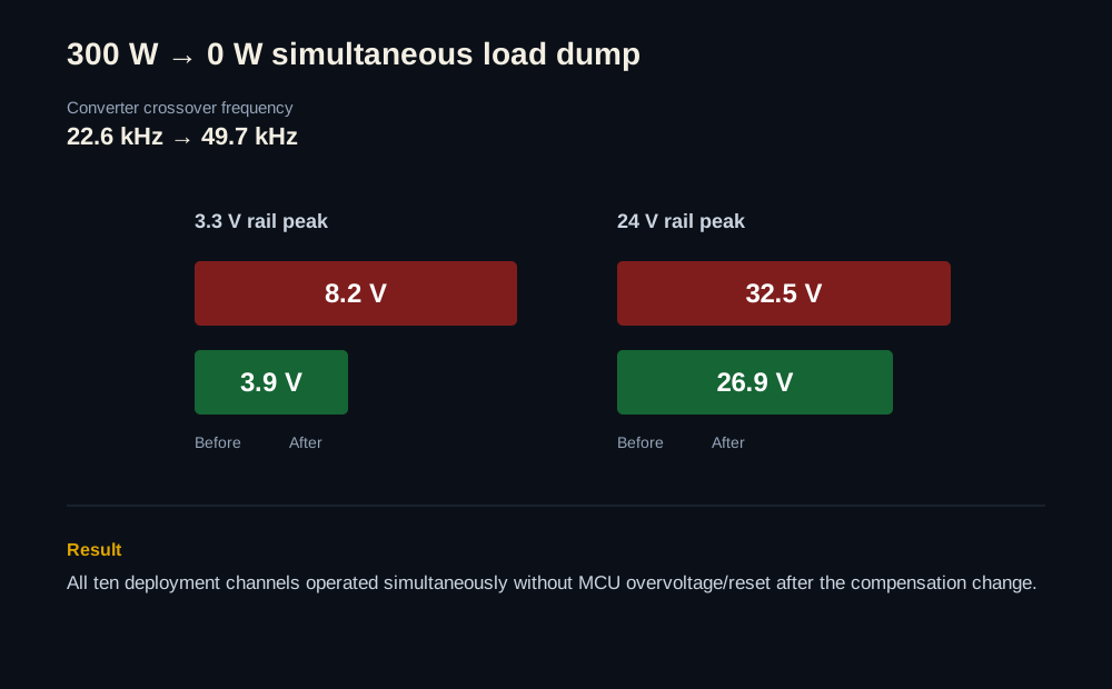
300 W → 0 W
Simultaneous Load Dump
2
Independent Power Trees
A six-layer recovery controller built around two power trees, three independent STM32 domains, hardware voting, local sensing, and ten 24 V deployment channels. I owned the board end to end, from architecture and layout through bring-up and the full ten-channel deployment test.
This page shows the architecture, layout, and bench results I can share publicly; a few team-internal implementation details are left out.
Hardware & test evidence
Measured
Measured 24 V efficiency during Rev 5 bring-up; the sweep peaked at 95.62% at 144 W external load.
Validated
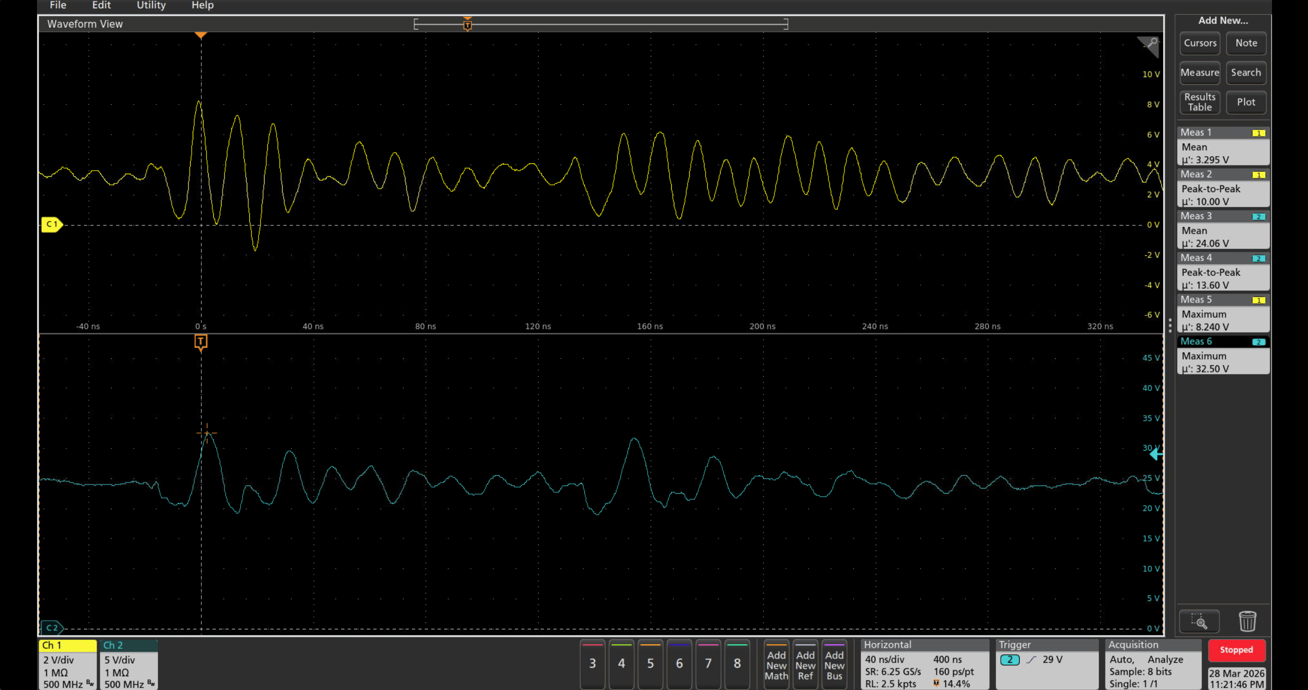
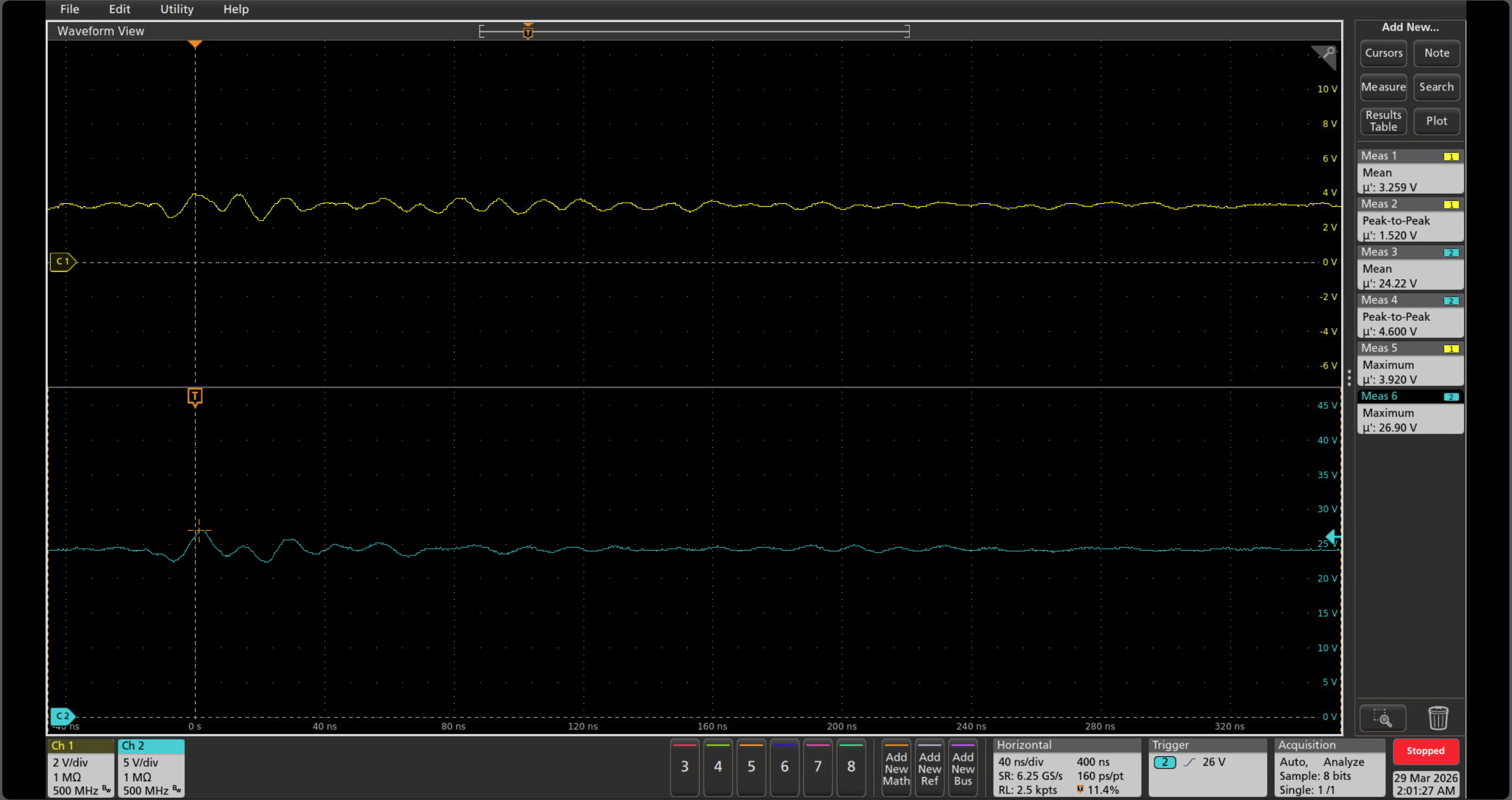
When all ten deployment loads turned off together, the load dropped from about 300 W to 0 W. Retuning the 48 V → 24 V converter cut the 3.3 V peak from 8.2 V to 3.9 V and the 24 V peak from 32.5 V to 26.9 V.
Integration
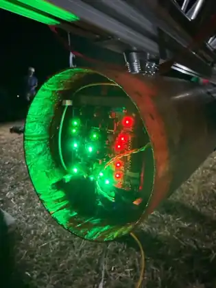
Recovery Rev 5 installed in the rocket with the real harnessing around it.
Validation
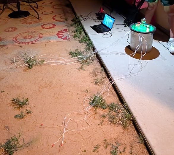
The full ten-channel deployment setup used to reproduce and then validate the worst-case transient.
Test history
Check that the control electronics stay within safe rail limits when all ten deployment loads turn off together.
The scope captures are from the same ten-channel test before and after the compensation change.
Initial bring-up
Assembled
The first simultaneous-deployment run exposed a slow upstream transient response and large rail overshoot.
Compensation update
Validated
I retuned the converter compensation and reran the same ten-channel event without the MCU overvoltage/reset condition.
RBF hot-plug rework
Validated
Hot-plugging the RBF tag produced a transient large enough to kill one STM32. I isolated the failure, moved further testing to another Rev 5 copy, and validated a series-damping fix with an inline resistor rework. A proper PCB footprint is planned for the next revision.
Design deep dives
Power
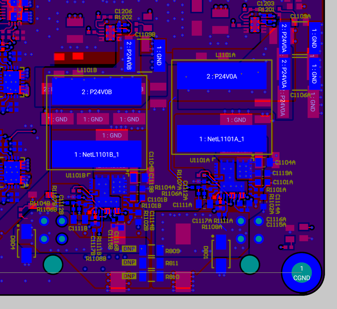
300 W → 0 W Load DumpHow the two power trees are split up, where they intentionally come back together, and what changed after the 300 W deployment transient exposed a control-loop problem.
Safety Architecture
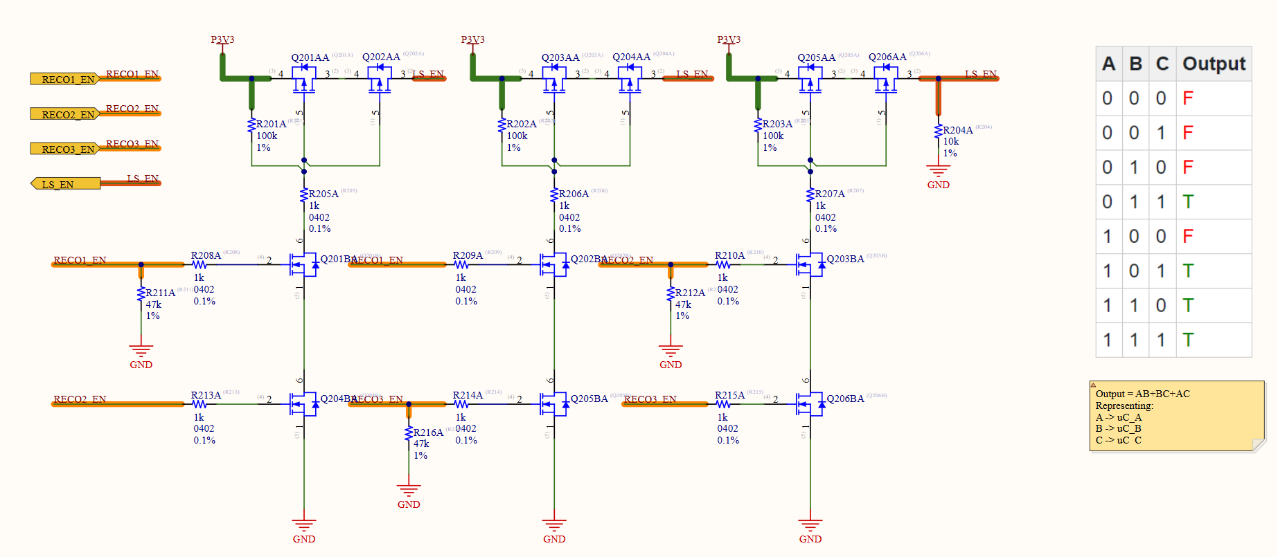
3 MCU DomainsHow the three STM32 domains, discrete voter, and hardware inhibits work together so one controller cannot fire the system by itself.
High Current
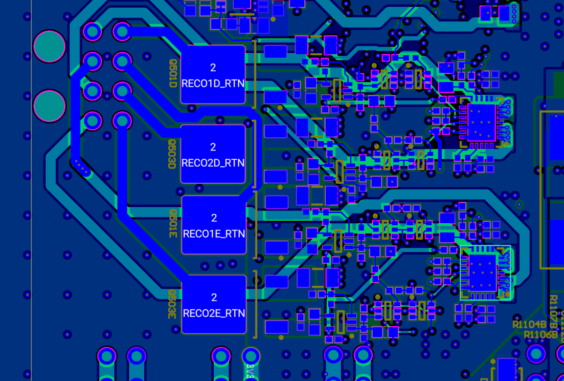
10 ChannelsHow the ten 24 V outputs are laid out, sensed, and tested as a bank instead of treating them like ten unrelated switches.