Fault-Tolerant Control
The basic rule is that one controller should never be able to fire Recovery by itself. Rev 5 gets there with three STM32 domains, local sensing, a discrete voter, and several hardware inhibits before the driver bank is allowed to turn on.
Three Independent Decisions
Each STM32 receives its own local sensor information and produces a deployment-enable decision. The three decisions remain separate until a discrete median voter.
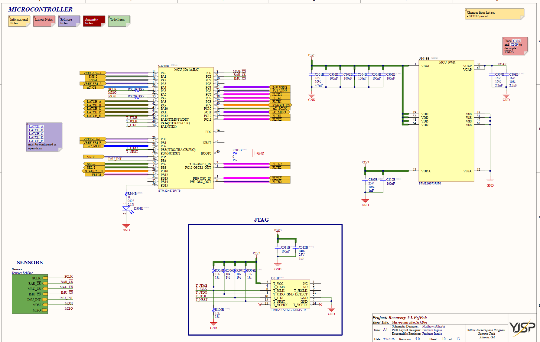
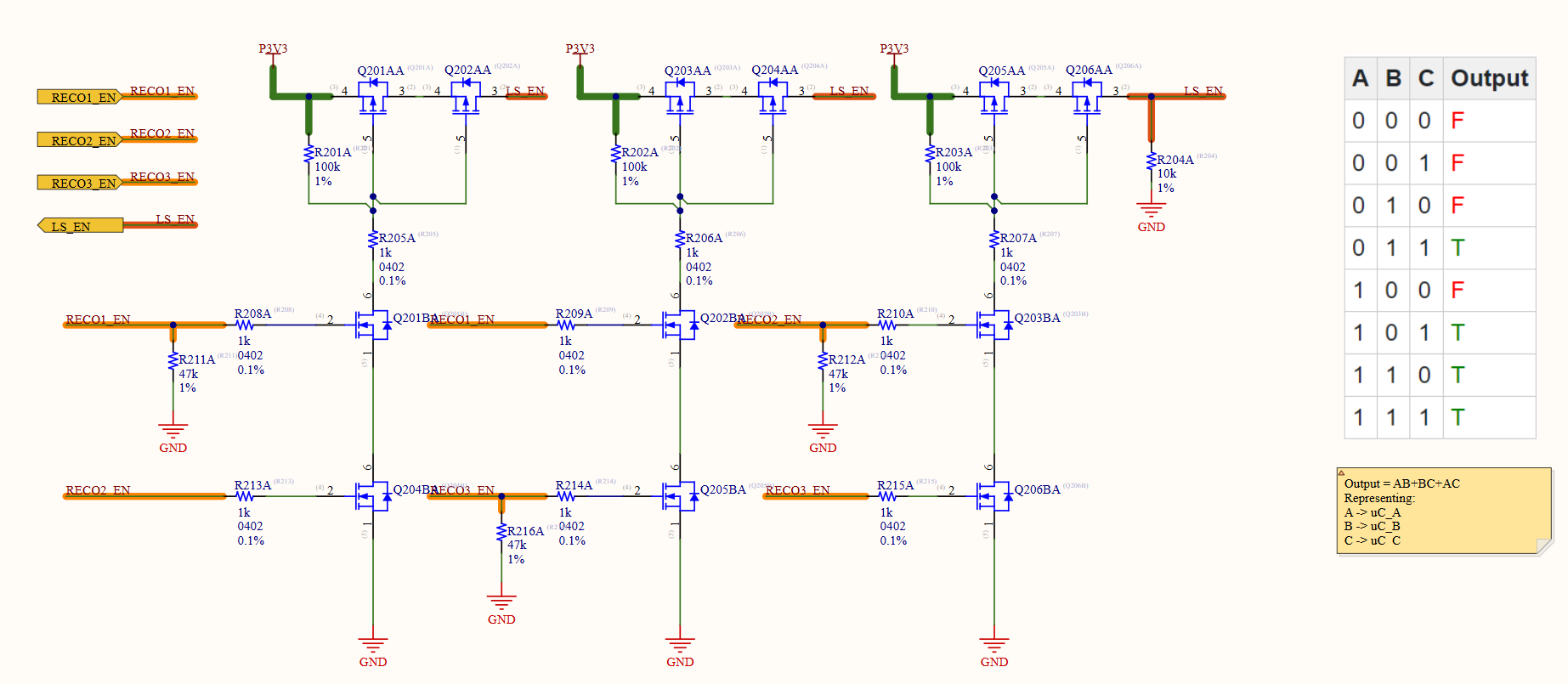
The voter implements:
OUT = AB + BC + AC
That means at least two controllers must agree before the shared deployment-enable path asserts.
| MCU A | MCU B | MCU C | Voted output |
|---|---|---|---|
| 0 | 0 | 0 | 0 |
| 0 | 0 | 1 | 0 |
| 0 | 1 | 0 | 0 |
| 1 | 0 | 0 | 0 |
| 0 | 1 | 1 | 1 |
| 1 | 0 | 1 | 1 |
| 1 | 1 | 0 | 1 |
| 1 | 1 | 1 | 1 |
A single stuck-high controller therefore cannot directly fire the system, while one failed-low controller still leaves the other two able to agree.
Hardware Inhibits
The voter is only one piece of the safety chain. RBF, ESTOP, abort, and software enables all give the system other ways to keep the drivers hard-off.
Physical Fault Domains
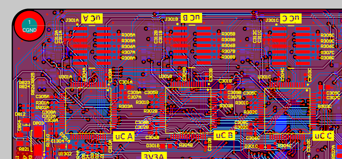
The PCB mirrors the logical architecture. The three MCU/sensor domains are kept physically distinct where practical, with local control routing maintained separately until signals intentionally converge at the voter/shared output stages.
Three MCUs do not buy much if one shared trace, reference, or power failure can break all three at once, so I tried to make the physical layout match the logical redundancy.
Bring-Up Sequence
I validated the board progressively rather than starting with live deployment loads:
- power-path and regulated-rail checks;
- independent MCU communication;
- local sensor interfaces;
- individual controller enables;
- voting truth-table behavior;
- RBF / ESTOP / abort inhibition;
- individual deployment channels;
- simultaneous deployment.
The final ten-channel test therefore exercised a control chain that had already been separated into its individual failure boundaries.
RBF hot-plug bug
The RBF path ended up being a good example of why I do not treat “hardware safing” as automatically safe just because the logic is simple.
The first plug/unplug cycle worked: the board powered with the RBF tag installed, removing the tag changed the safing state correctly, and nothing looked suspicious. When I plugged the tag back in, though, the hot-plug transient was large enough to kill one STM32.
I killed power immediately, removed the failed MCU, and verified that the rest of the board had not developed a short. From that point on I kept Reco-51 available for firmware and sensor bring-up and moved the destructive RBF debugging onto Reco-52, so one hardware problem did not block the software team.
The next day Reco-51 could still talk to all three STM32s and the attached sensors, and its ADC readings checked out. On Reco-52 I isolated the RBF issue and settled on a series damping resistor in the connector path.
There was no resistor footprint on Rev 5, so I physically cut the connector pins and inserted the resistor inline:
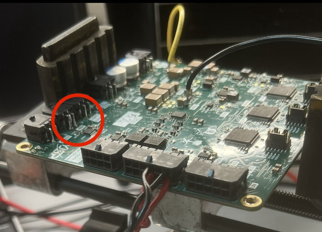
That is obviously a prototype rework, not the layout I would ship on another revision. The future-board change is to add the damping provision properly and make the full-length RBF harness hot-plug case an explicit validation step. Those are next-revision notes only; Rev 6 does not exist yet.
What This Architecture Buys
I am not claiming this magically removes every common-mode failure. What it does give me is a command path I can actually reason about and test: three separate decisions, a simple hardware voter, separate inhibits, and no single MCU with direct authority over the high-current outputs.