Integration
Assembled umbilical integration
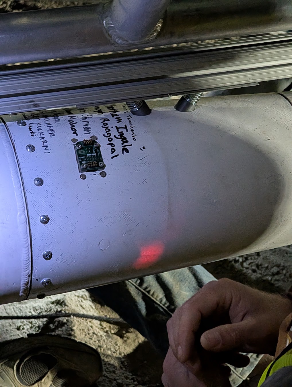
Darcy/Felicette umbilical installed at the real vehicle interface with the ground/flight breakaway connection in place.
Ground-to-vehicle magnetic pogo-pin interface for 48 V power, Ethernet, and safing across two launch vehicles
Responsible Engineer
Browse the exported schematic and design sheets.
Look through the copper layers and routing.
Spin around the board model in 3D.
The reasoning, bring-up, bugs, and test results behind the board.
Project overview
Vespula + Darcy
Vehicle Designs
0.3 V @ 48 V
Measured Drop
Power + Ethernet
Interface
Ground + Vehicle
PCB Pair
The magnetic breakaway umbilical I designed for both Vespula and Darcy/Felicette. A ground-side and vehicle-side PCB carry 48 V power, Ethernet, and safing/control through a compact pogo-pin interface that has to work electrically and also detach cleanly at launch.
I designed both the Vespula and Darcy/Felicette umbilicals. The embedded schematic is the Darcy/Felicette version because that is the one I currently have uploaded here.
Hardware & test evidence
Integration
Darcy/Felicette umbilical installed at the real vehicle interface with the ground/flight breakaway connection in place.
Test history
Measure the drop through the entire assembled ground-to-vehicle power path, not just the PCB copper.
Check the actual assembled electrical/mechanical interface before using it on the vehicle.
Vespula implementation
Validated
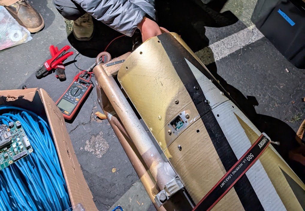
Designed the original ground-side and vehicle-side magnetic pogo-pin umbilical for 48 V power, Ethernet, and launch/integration interfaces.
Darcy / Felicette implementation
Validated
Designed the second vehicle version on the same mechanical platform, adding the required RBF/safing allocation and revising the PCB copper/via implementation while preserving structural compatibility.
Design deep dives
Architecture
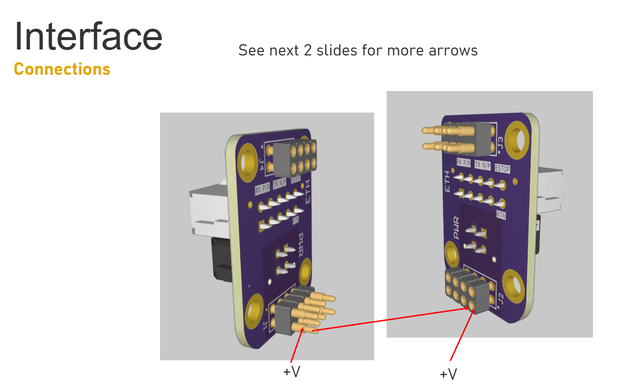
2 vehiclesHow I reused one compact two-board mechanical platform across two vehicles while changing the electrical pinout where the missions differed.
Electrical
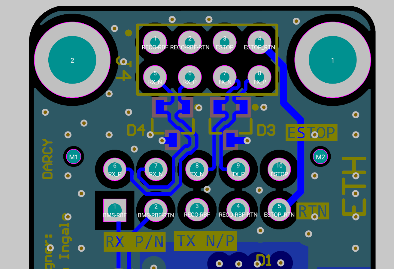
0.3 V dropHow 48 V and Ethernet share the same pogo interface, plus the measured 0.3 V drop through the complete power path.
Integration
Ground ↔ FlightHow the pogo alignment, magnets, orientation, and release direction became part of the electrical-reliability problem.