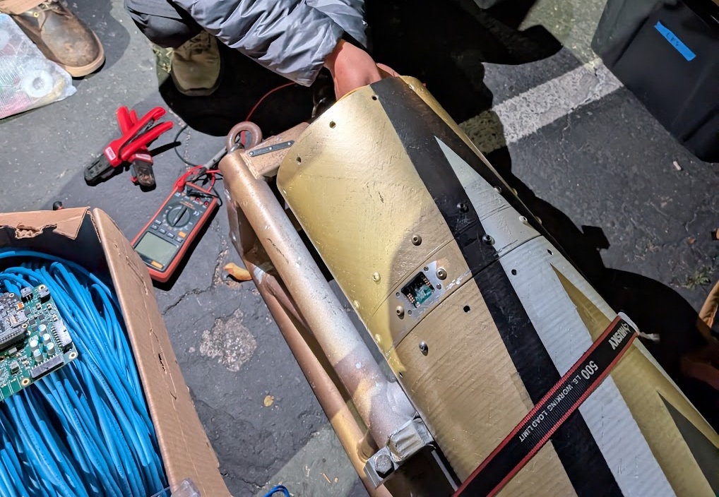
Magnetic Mating & Vehicle Integration
The weird thing about an umbilical is that disconnecting is part of the job. That makes the mechanical behavior part of the electrical-reliability problem too.
Pogo + Magnet Interface
The boards use pogo contacts for the electrical connection and strong magnets for retention. The PCB geometry therefore controls:
- contact alignment;
- mating orientation;
- retention force direction;
- strain transferred into the vehicle-side board/harness;
- the direction the interface releases.
Preventing Integration Errors
I tried to make the correct orientation obvious without needing someone to stop and stare at a drawing. Connector placement, polarity, and the mechanical shape all help make a bad mate harder.
Flight-Like Validation
I did not validate this as two loose PCBs on a desk. I checked it with the actual ground/vehicle hardware and harnessing:
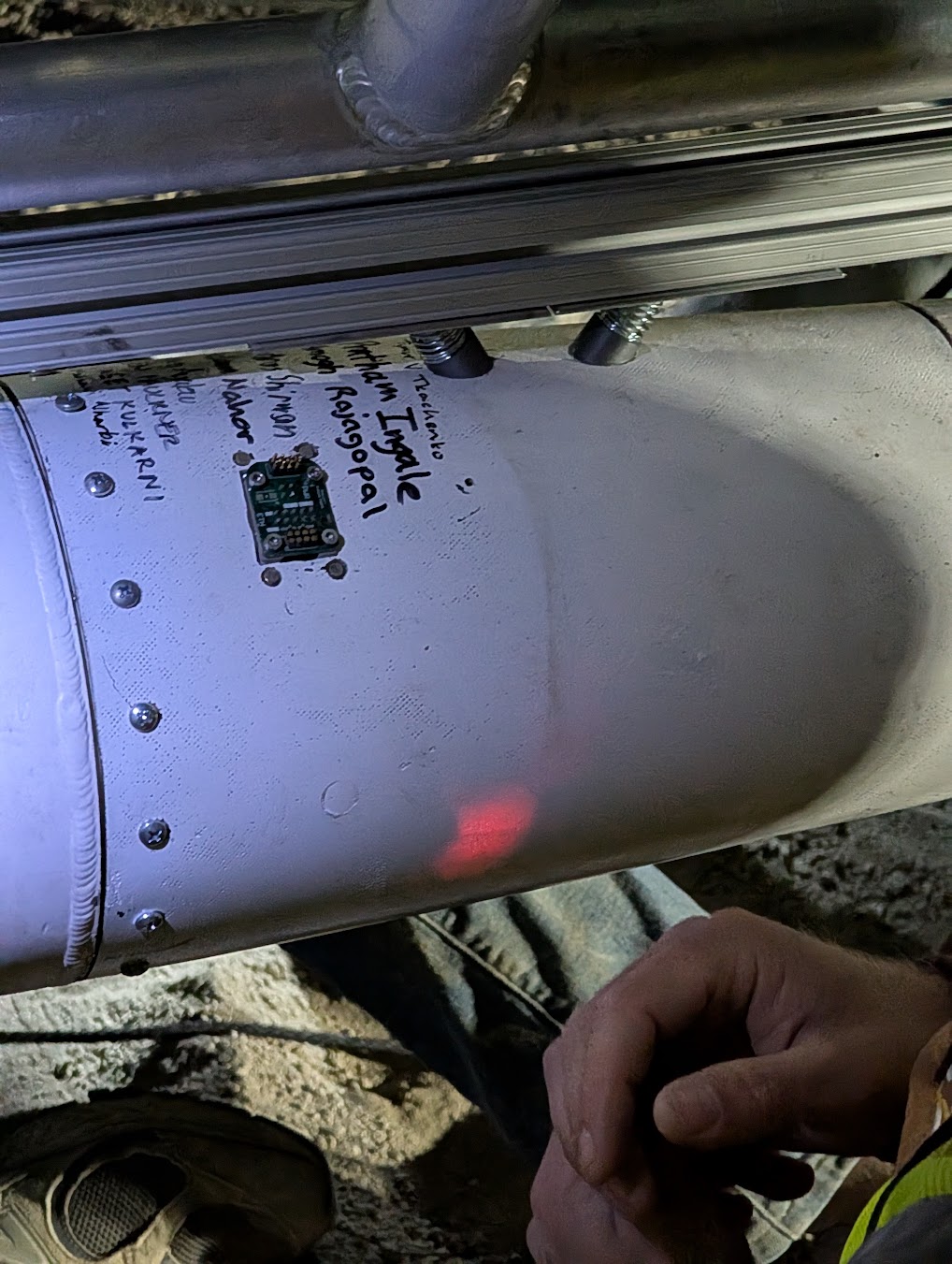
- repeated mate/detach behavior;
- Ethernet link after assembly;
- safing/control continuity;
- power transfer;
- release behavior.
Two Vehicles, One Envelope
Both Vespula and Darcy/Felicette use the same basic structural interface. Keeping that envelope fixed while redesigning the vehicle-specific electrical allocation meant the second vehicle did not need a new umbilical mounting concept.
The part I like most is that the second vehicle could change electrically without throwing away a mechanical interface that already worked.