Power & Ethernet Through the Breakaway
The same pogo boundary has to carry both 48 V ground power and Ethernet, which is kind of an awkward combination. They fail in completely different ways, so I did not treat them like one routing problem.
48 V Path
For the power side, the number I actually care about is the resistance of the entire assembled path:
ground connector → ground PCB → pogo contacts → vehicle PCB → vehicle connector
A trace-width calculation does not know anything about pogo/contact resistance, so I measured the finished interface pin to pin instead.
Measured power transfer
Before
48.0 V
After
47.7 V
0.3 V total drop across the complete assembled umbilical path.
The useful result is the simple one: with the real boards and contacts in the loop, I only lost 0.3 V across the full path.
Ethernet Path
Ethernet wants basically the opposite thing from the power path: not huge copper, but a clean differential transition and a sane return reference.
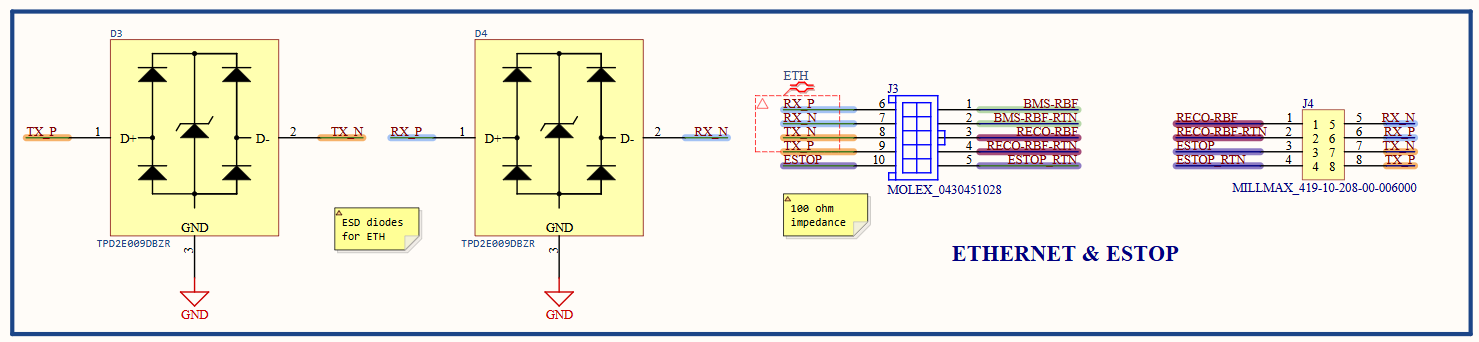
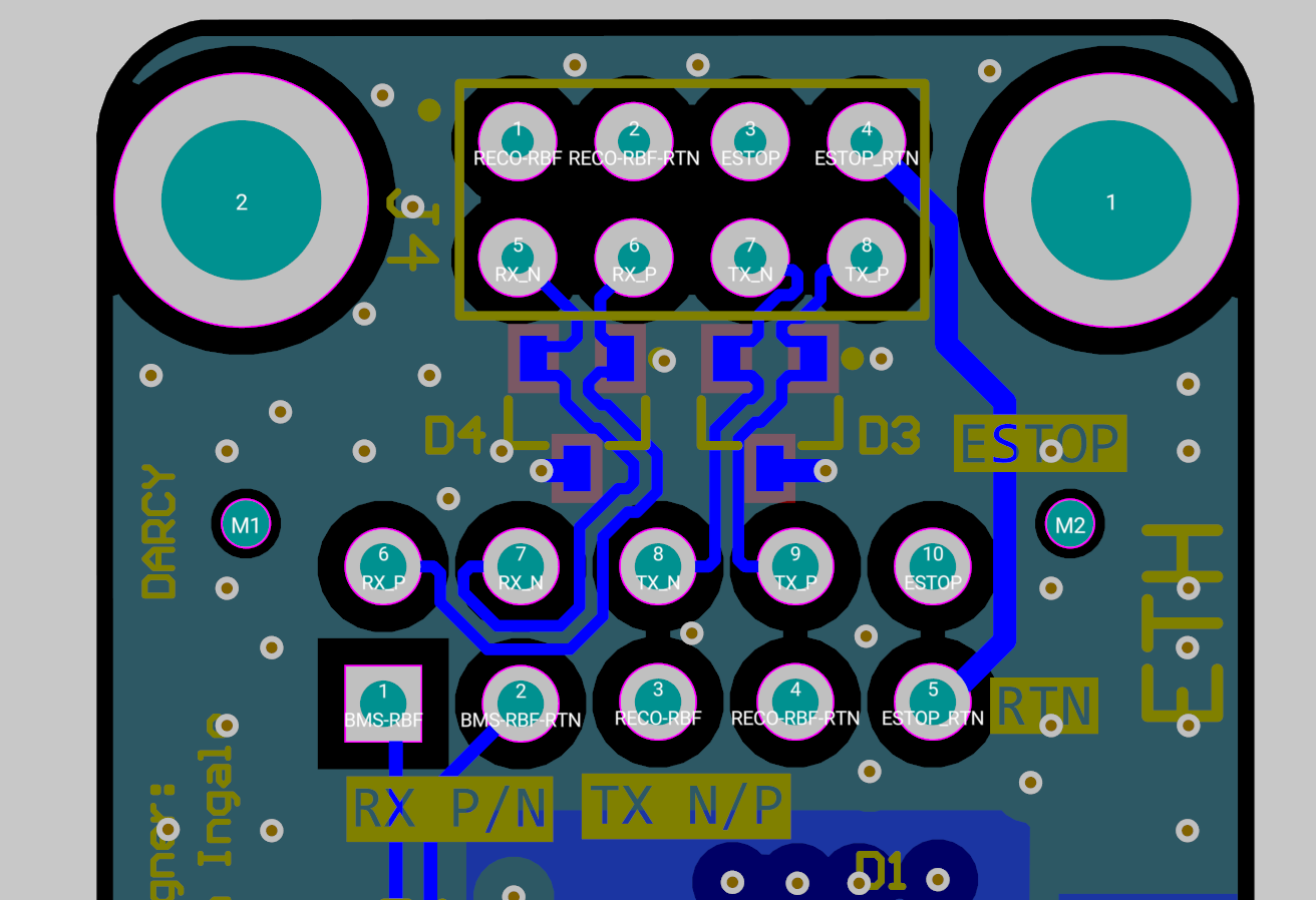
I kept the pair transition compact, preserved pair assignment through both PCBs, minimized unnecessary stubs, and kept the path referenced as it crossed the connector region.
I checked Ethernet through the fully assembled pogo interface so the test included the real contact geometry, not just two PCBs sitting on the bench.
Protection
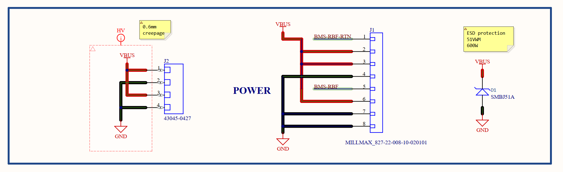
Because the umbilical is repeatedly handled during integration, the externally exposed power and Ethernet paths include transient/ESD protection close to the interface.
The idea is to eat the ugly cable/handling transient at the interface instead of letting it wander deeper into the avionics stack.