Vespula / Darcy Umbilical Engineering Notes
System
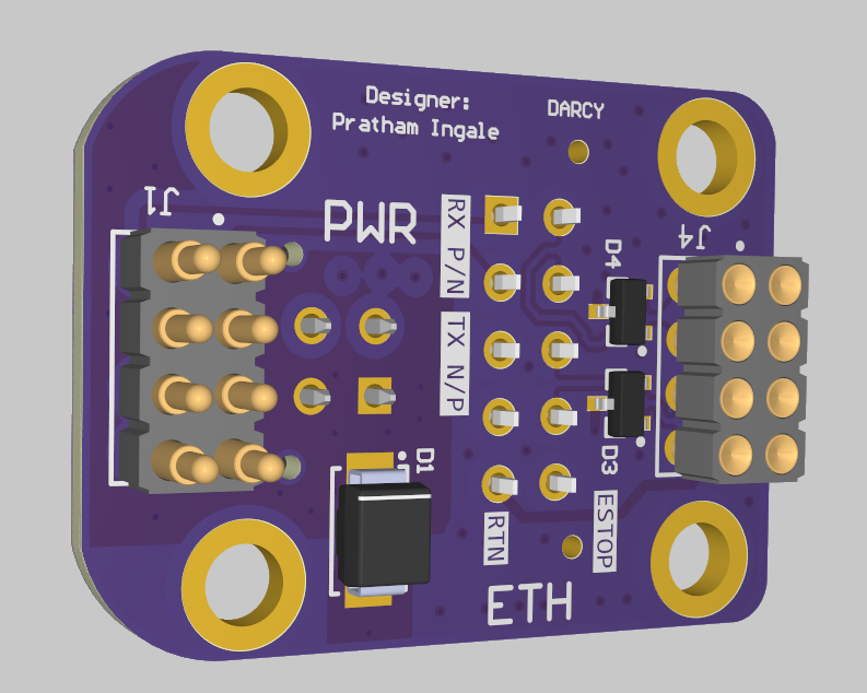
The umbilical is the temporary electrical link between ground support equipment and the vehicle. I designed the versions used on both Vespula and Darcy/Felicette.
Each vehicle uses two small PCBs:
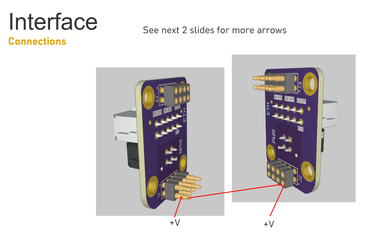
ground harness → ground-side PCB ⇄ magnetic pogo interface ⇄ vehicle-side PCB → vehicle harness
Through that one breakaway connection I had to carry 48 V ground power, Ethernet, and vehicle-specific safing/control signals.
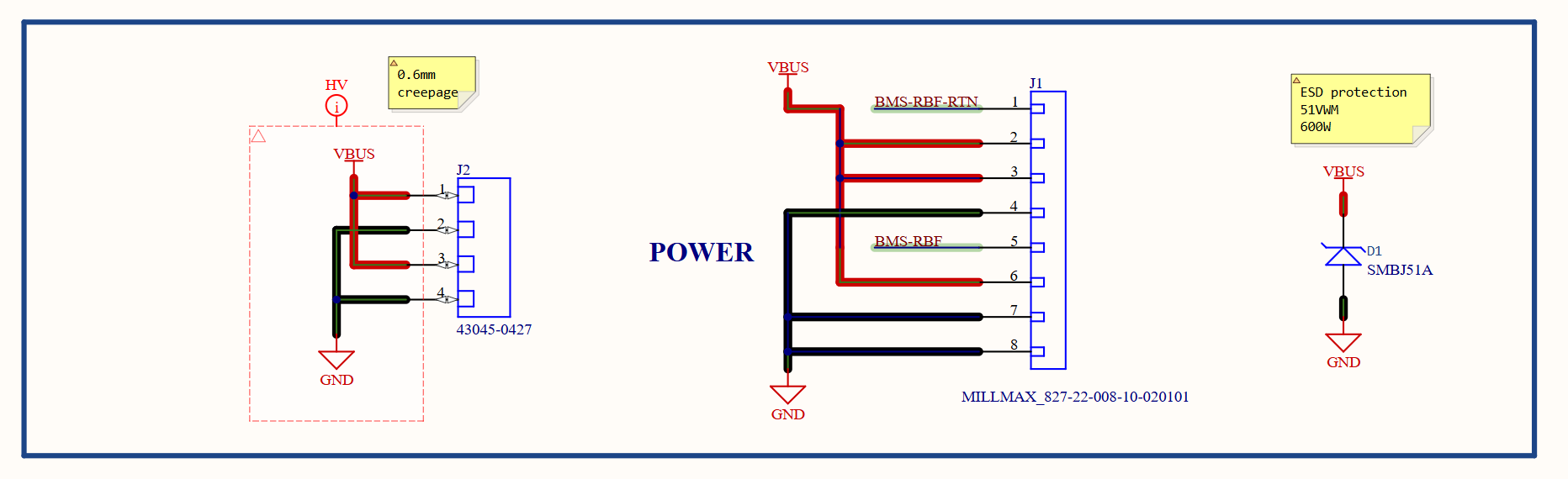
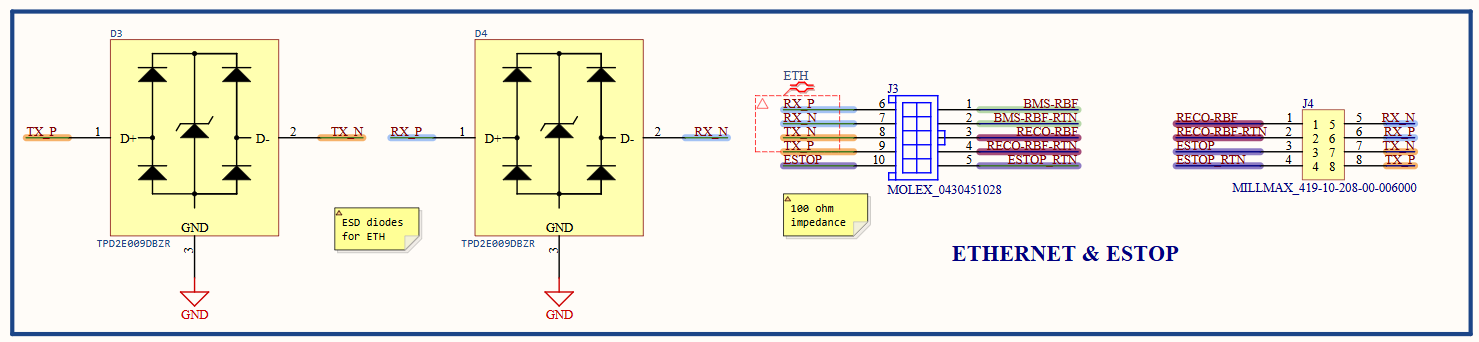
The schematic shown here is the Darcy/Felicette version, but the project covers both designs.
What I Designed
Both versions share the same basic setup:
- ground-side and vehicle-side PCBs;
- magnetic pogo-pin mating;
- roughly 2 in × 1.5 in boards;
- ground-power transfer;
- Ethernet pass-through;
- transient/ESD protection;
- constrained mating orientation and release.
Vespula was the first full implementation. For Darcy/Felicette, I kept the mechanical envelope the same and changed the safing/RBF pin allocation and copper/via implementation around the new vehicle requirements.
48 V Power Path
The power path is more than a trace-width problem. Connector resistance, pogo contacts, PCB copper, and the harness all show up in the voltage the vehicle actually receives.
So I measured the whole assembled path pin to pin.
Complete umbilical power path
Before
48.0 V input
After
47.7 V output
Measured drop across the ground-side PCB, pogo interface, vehicle-side PCB, and connector path was 0.3 V.
I care more about that number than a theoretical copper-drop estimate because it includes the real interface.
Ethernet
Ethernet has a completely different set of problems from 48 V power, even though both have to cross the same tiny connector boundary.
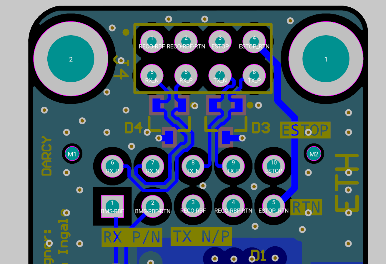
I kept the pair transition compact, preserved the pair assignment across both boards, avoided unnecessary stubs, and kept a usable return reference around the connector region.
I validated Ethernet through the fully assembled interface, not just on two loose PCBs.
Safing / Control
The two vehicles do not use the exact same control signals, so I kept the common mechanical/PCB platform separate from the vehicle-specific pin assignment.
Darcy/Felicette needed both RBF1 and RBF2 through the umbilical. Since that vehicle did not need the same power-contact population as Vespula, I repurposed some contacts and then reworked the copper/via geometry around the new allocation.
Mechanical Interface
This is one of those designs where the schematic can be correct and the product can still be bad. If the pogo interface is easy to misalign, awkward to mate, or puts load into the vehicle PCB when it releases, that is still an electrical reliability problem.
So I designed around:
- obvious mating orientation;
- magnetic retention;
- controlled pogo alignment;
- tight airframe packaging;
- predictable release direction;
- repeated mate/detach use during integration.
Keeping the mechanical envelope the same between vehicles saved the Structures side from having to redesign the mount every time the electrical pinout changed.
Validation
I validated the full interface as a system:
- correct power polarity/path;
- 0.3 V measured drop at 48 V pin to pin;
- Ethernet through the assembled interface;
- safing/control continuity;
- repeated mating and release;
- integration with the actual harnessing/mechanical hardware.
That is the part that matters most to me on an umbilical: every function still has to work after going through the exact breakaway hardware the vehicle uses on the pad.