Shared Vehicle Interface
I designed the umbilical as a two-PCB system, not just a connector breakout. The ground-side and vehicle-side boards together are the actual electrical/mechanical handoff between GSE and the vehicle.
Common Platform
The Vespula and Darcy/Felicette implementations share the same core architecture:
GSE harness → ground PCB → magnetic pogo interface → vehicle PCB → flight harness
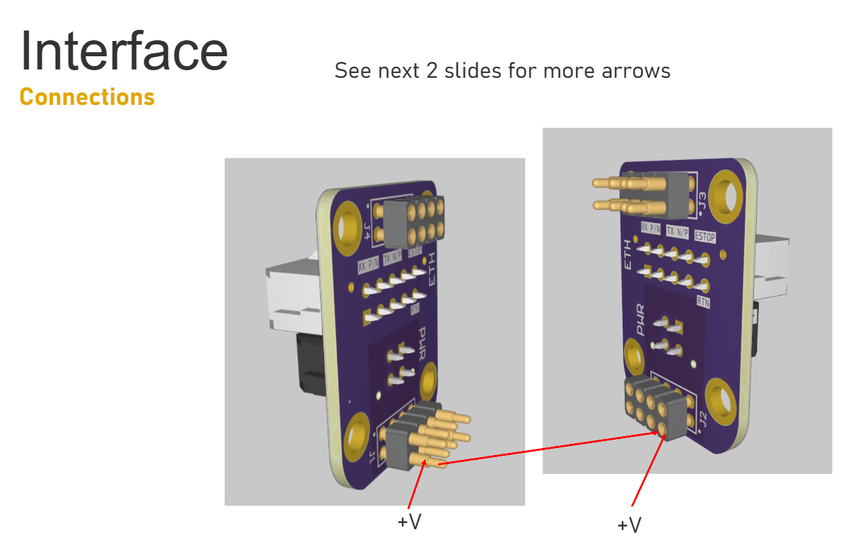
That common boundary carries three different classes of signal:
- 48 V vehicle power;
- Ethernet;
- mission-specific safing/control.
The annoying part is that power, Ethernet, and safing all want different things electrically, but they still have to fit through the same tiny breakaway interface.
Reuse Across Two Vehicles
I designed both vehicle versions. Vespula established the ground/flight two-board architecture and connector geometry. The Darcy/Felicette implementation reused that mechanical envelope while changing the signal allocation to support its additional RBF requirements.
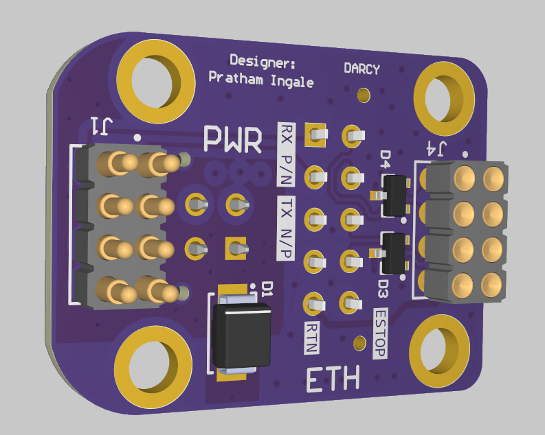
I kept the outline, pogo geometry, and structural interface fixed on purpose. That let the electrical pinout change without making Structures and ground ops relearn the whole interface.
Vehicle-Specific Allocation
The Darcy/Felicette design needed both RBF1 and RBF2 through the interface. I reallocated contacts from VBUS/GND where the lower current requirement allowed it, then revised the copper/via implementation around the new assignment.
I like this as an example of reuse because it was not just 'Rev B of the same board.' The mechanical platform stayed the same while the electrical allocation changed for a different vehicle.