Architecture
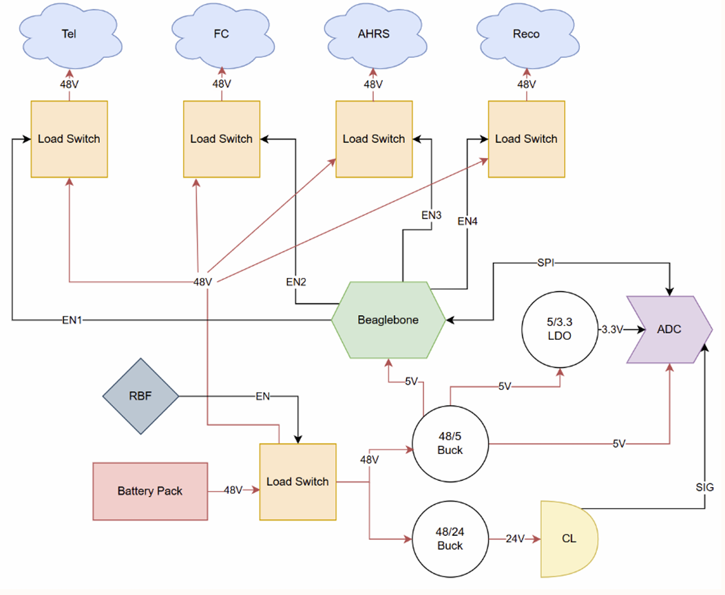
System power architecture
A simpler block-level view of how battery power, switched outputs, local rails, control, and telemetry fit together.
Protected 12-cell battery interface and monitored power-distribution node for vehicle avionics
Design Responsible Engineer
Browse the exported schematic and design sheets.
Look through the copper layers and routing.
Spin around the board model in 3D.
The reasoning, bring-up, bugs, and test results behind the board.
Project overview
12S Li-Ion
Battery Source
5
Controlled Load Paths
Current + Voltage
Power Telemetry
4
Copper Layers
A four-layer battery-management and power-distribution board between the 12S pack and the Darcy avionics. I designed the schematic and PCB, ordered and assembled the hardware, then brought up the protected input, five switched outputs, and measurement paths.
This is the actual Darcy BMS I designed and brought up. The old unrelated 'Darcy BMS Debugging' page is not used anywhere in this case study.
Hardware & test evidence
Architecture
A simpler block-level view of how battery power, switched outputs, local rails, control, and telemetry fit together.
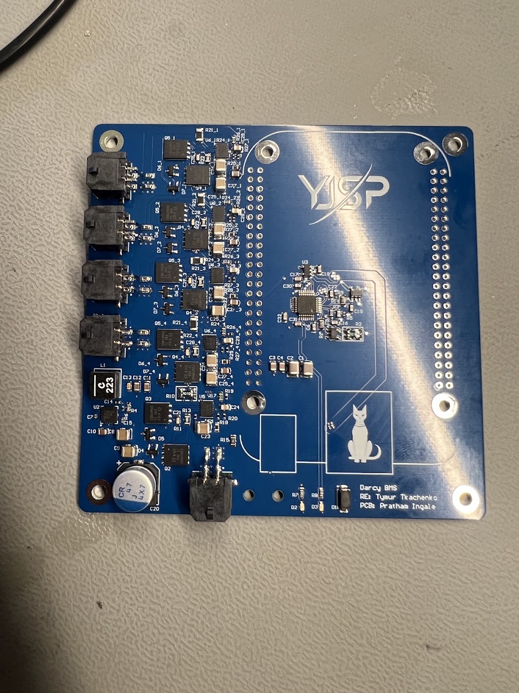
Built
The assembled four-layer BMS I used for protected-input and controlled-output validation.
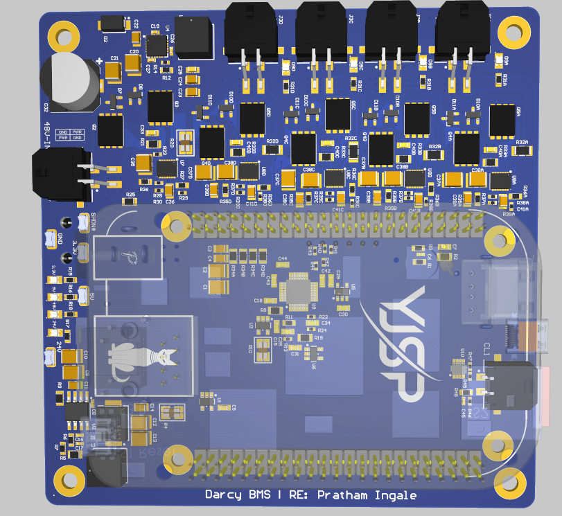
PCB
Altium 3D view of the BMS and power-distribution PCB.
Test history
Verify that the battery-input protection and switching path operates correctly before downstream loads are energized.
Verify that the five downstream power outputs can be independently enabled and disabled through the board's switched distribution architecture.
Design
Designed
Completed schematic and PCB layout for the protected battery input, auxiliary power, five controlled outputs, measurement paths, and vehicle interfaces.
Fabrication + assembly
Assembled
Boards were ordered and assembled, then brought up in stages before integrated testing.
Hardware validation
Validated
Protected input behavior and downstream output switching were exercised successfully on the assembled board.
Design deep dives
Power
12S inputHow battery power enters the board, where protection lives, and how I kept the higher-current paths separate from the measurement side.
Distribution
5 outputsWhy I used five independently switched outputs and how I kept the software-visible power state tied to a real, tested hardware output.
Validation
Built + testedThe staged bring-up flow, including the input load-switch issue that turned out to be soldering rather than a design problem.