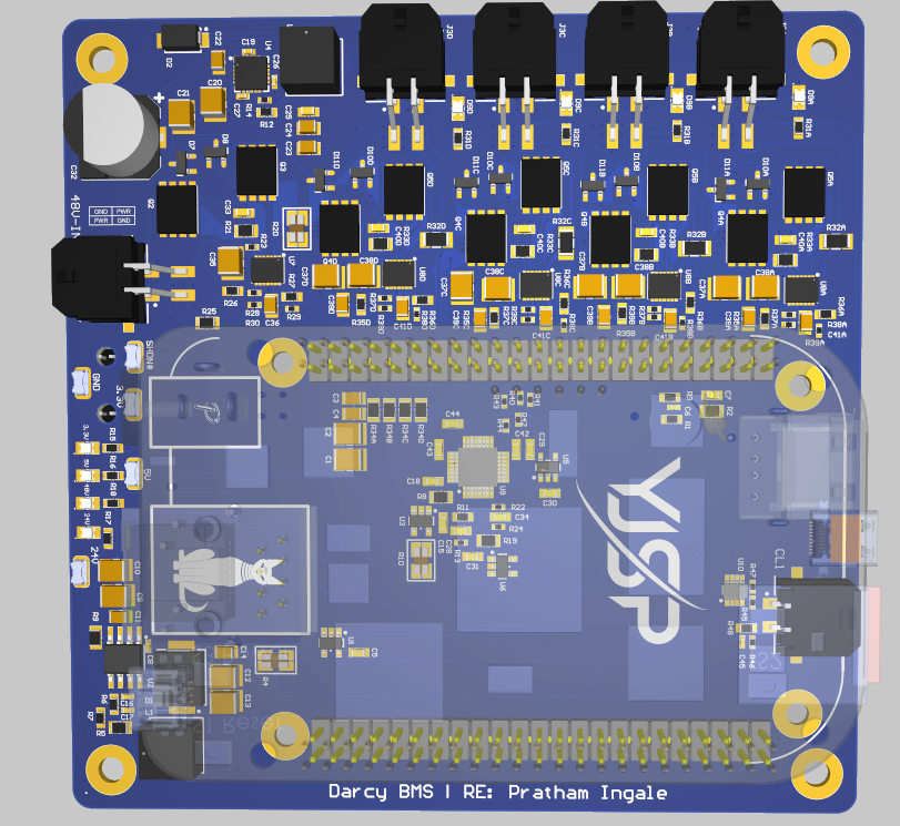
Output Switching & Telemetry
The Darcy BMS has five controlled output paths, so power state is something the avionics can actually command instead of a fixed wiring decision.
Why Individual Outputs
Having separate channels means I can:
- sequence subsystems during startup;
- power one load during bench testing;
- remove a faulted branch without immediately losing every avionics load;
- verify expected load behavior before vehicle operation;
- create repeatable integration procedures.
The repeated channel design also made bring-up nicer: once one channel made sense, I could check the same behavior across the rest instead of debugging five unrelated circuits.
Measurement Chain
The board measures voltage/current behavior around the distribution system and interfaces with current-loop sensing.
That measurement path is intentionally treated differently from the switched power path. Sense routing, filtering, and ADC inputs are kept quiet while the distribution copper is sized and routed for load current.
Hardware Validation
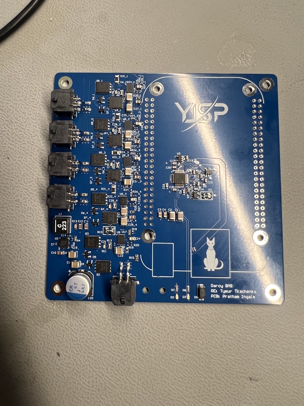
I brought the outputs up one at a time on the assembled board before using combined vehicle loads. The checks verified that each commanded channel could transition between enabled and disabled states while the input protection remained stable.
The important part is that the software-visible power state maps to a real switched output I actually exercised on the assembled board, not just a nice net name in Altium.