Protected Power Architecture
The Darcy BMS is basically the point where raw 12S battery power becomes controlled vehicle power. I did not want the pack hard-wired straight into every downstream connector, so battery power first goes through a protected input stage and only then reaches the auxiliary rails and switched outputs.
Why the Boundary Matters
A bad battery-side condition and a bad downstream load are two different problems, so I did not want them handled by one giant all-or-nothing switch. The input side needs to protect the vehicle from abnormal source/current conditions, while each downstream branch needs to remain controllable without forcing the entire avionics system off.
That drove a layered architecture:
12S battery → protected input → distribution bus → controlled outputs / auxiliary rails / measurement
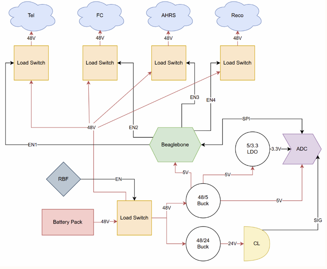
Protected Input
The protected input gives me one clear place to decide whether the rest of the vehicle should get power at all before I start turning on individual branches.
During bring-up, I found one issue on this path that was ultimately traced to assembly/soldering rather than the circuit itself. After rework, I reran the same staged checks and validated the protected input behavior before moving on to the output channels.
PCB Implementation
The four-layer layout has to carry vehicle current while preserving low-level measurement quality.
<Figure src="/content/projects/darcy-battery-management-system/media/darcy-bms-3d-altium-view.png" alt="Darcy BMS Altium 3D view" caption="The four-layer BMS and power-distribution PCB in Altium 3D." /> The important current paths are the battery entry, protected switch, branch distribution, connector outputs, and return geometry—not simply the size of the copper pours.