Bring-Up & Debug
Once the board was built, the first job was figuring out whether a weird behavior was actually my circuit or just an assembly problem before I started redesigning anything.
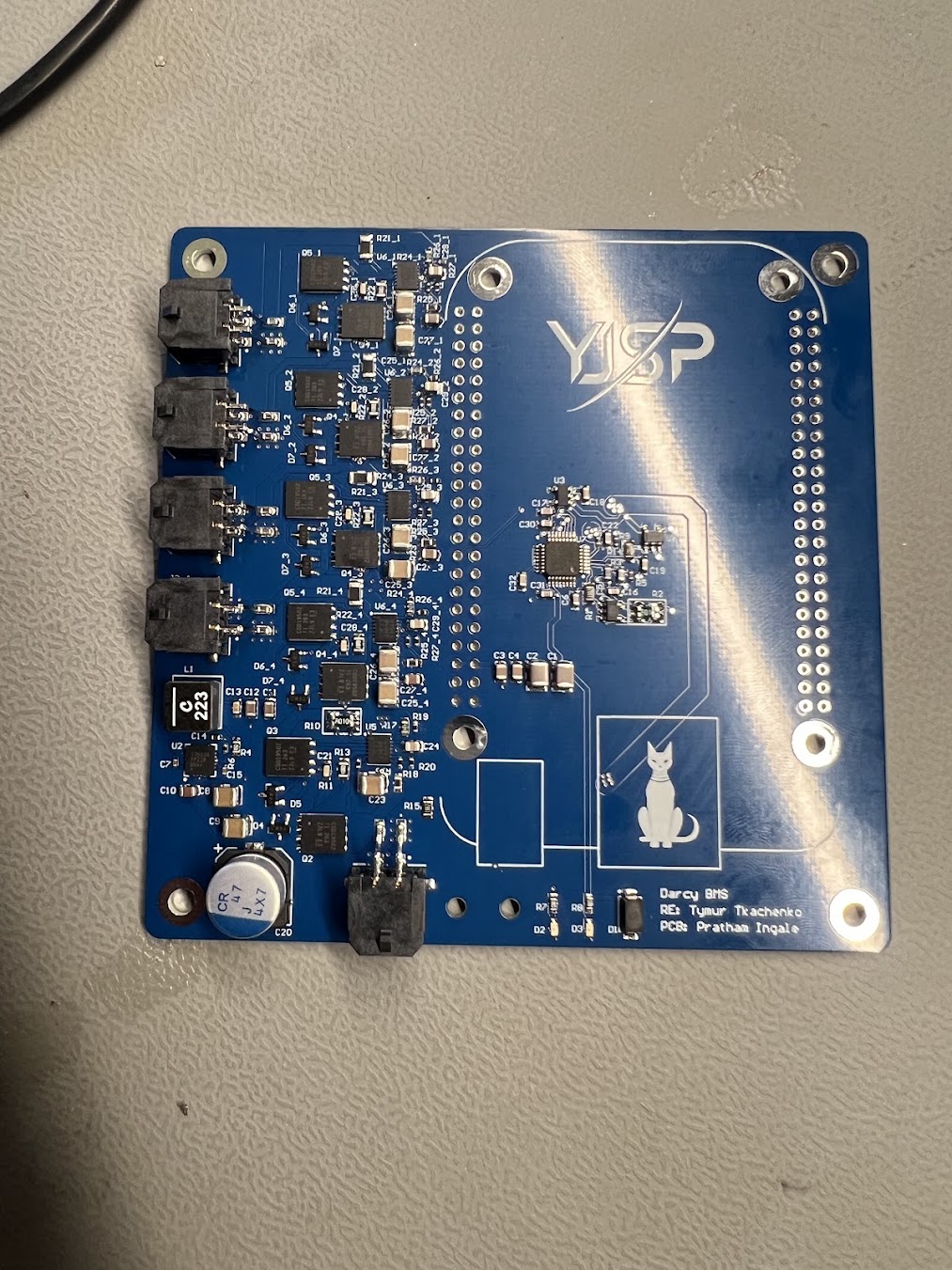
Staged Power-Up
I used a current-limited source and brought the board up in layers:
- dead-board resistance and polarity checks;
- protected battery input;
- auxiliary rails;
- individual switched outputs;
- telemetry/measurement paths;
- representative downstream loading.
Input Load-Switch Finding
One early issue appeared on the protected input/load-switch path. The stage did not behave as intended, but the root cause was not the schematic architecture—it was an assembly/soldering problem on the input load-switch hardware.
This was exactly why I was bringing it up one block at a time. I isolated the stage, fixed the soldering, and reran the exact same check before moving on.
Validation Result
After rework, the board proceeded through protected-input and output-switch validation. The controlled outputs were exercised on assembled hardware before integration.
The useful lesson was not 'check your soldering.' It was that a structured bring-up flow kept a simple manufacturing problem from turning into an unnecessary circuit redesign.