Darcy Battery Management System Engineering Notes
Purpose
The Darcy BMS sits between the vehicle's 12S battery and the rest of the avionics. I designed the schematic and four-layer PCB, ordered it, brought it up, debugged it, and validated the protected input and switched outputs before integration.
Basically, this is the board where battery power becomes controlled vehicle power.
Architecture
The board includes:
- a protected battery-input path;
- auxiliary power regulation;
- five independently controlled output paths;
- connector-level power switching;
- voltage and current telemetry;
- ADC conditioning;
- current-loop sensor interfacing;
- vehicle/debug connectors.
I liked the repeated output-channel structure because it made bring-up much less scary: I could turn on one branch at a time instead of energizing the whole vehicle at once.
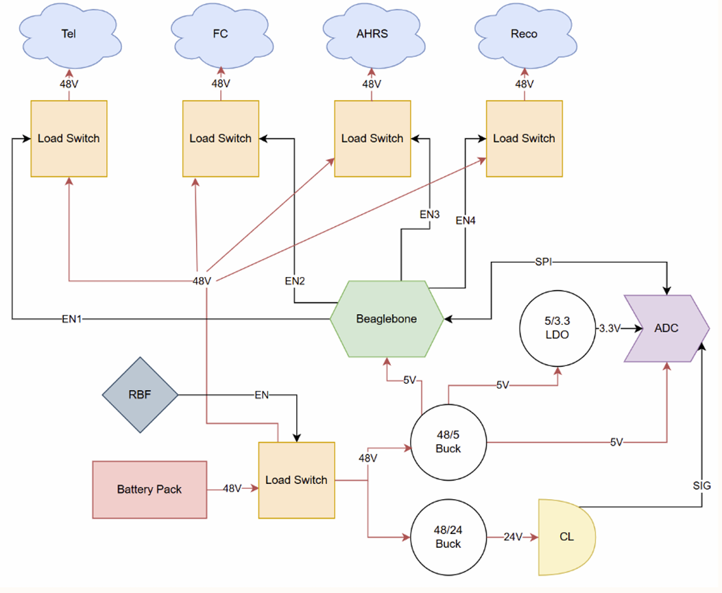
Protected Input
Battery power first goes through a protected switching path before it reaches the rest of the distribution bus.
One of the early bring-up issues looked like the input load switch was behaving incorrectly. It turned out the circuit was fine—the part was not soldered properly. After rework, I reran the same checks and the protected input behaved normally.
Switched Distribution
There are five controlled load paths instead of one always-on bus. That lets the vehicle:
- sequence subsystems;
- isolate one bad branch;
- test one output at a time;
- compare expected and abnormal load behavior;
- explicitly control power state from avionics.
I exercised the outputs channel by channel on the assembled board before integration.
Telemetry
The same board also measures voltage/current behavior around the distribution system.
That means there are two very different current scales living on one PCB: the actual vehicle-power paths and the low-level measurement paths. I kept the high-current routes direct and tried not to make the ADC/measurement inputs share ugly return paths with switching loads.
Bring-Up
My bring-up sequence was:
- check polarity and resistance before power;
- apply current-limited battery-equivalent input;
- verify the protected input;
- verify the auxiliary rails;
- enable one output at a time;
- check switching/protection behavior;
- validate the measurement interfaces;
- repeat with the real vehicle interfaces.
That sequence is what made the load-switch assembly issue obvious before it turned into a much bigger debugging session.
Result
The board was ordered, assembled, and validated. After the input-switch rework, the protected input and controlled outputs both behaved correctly and the board moved into actual vehicle use.