System Architecture
This page is basically the 'who owns what?' view of the LR2021 telemetry system. I want someone looking at it later to be able to tell where flight data comes from, what the CM5 owns, what crosses board boundaries, and which RF states are actually legal.
Data Flow
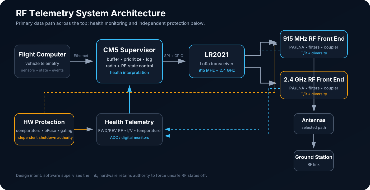
| Link | Interface | Purpose |
|---|---|---|
| Flight computer → CM5 | Ethernet | Move vehicle telemetry into the communications subsystem |
| CM5 → LR2021 | SPI + control GPIO | Configure the radio, load packets, select mode, and service interrupts/status |
| CM5 → RF front end | GPIO / enables | Sequence PAs, LNAs, T/R switches, and antenna-selection switches |
| Sensors/monitors → CM5 | ADC / digital telemetry | Report current, voltage, temperature, forward power, reflected power, and fault state |
| Hardware protection → RF front end | Direct logic / power control | Force unsafe RF loads off independently of software |
Responsibility Split
I do not want the Flight Computer caring about PA enables, T/R switches, or detector details. It should hand over telemetry and let the comms subsystem deal with the RF-specific mess. The CM5 owns buffering, radio configuration, RF-state sequencing, health interpretation, and logging. The LR2021 owns the modem/transceiver function, while the external RF front end provides the gain, filtering, switching, diversity, and high-power sensing that the radio alone does not provide.
Operating Modes
| Mode | Purpose | Required RF state |
|---|---|---|
| Safe / standby | Boot, fault handling, or no active link | PAs off; LNAs off unless explicitly required; switch state known |
| RX 915 | Long-range receive | 915 receive path enabled; all TX PAs off |
| TX 915 | Long-range transmit | 915 TX path selected; 915 PA enabled only after switches settle |
| RX 2.4 | Higher-rate receive | 2.4 receive path enabled; all TX PAs off |
| TX 2.4 | Higher-rate transmit | 2.4 TX path selected; 2.4 PA enabled only after switches settle |
| Fault hold | Unsafe thermal/electrical/RF condition | Affected PA or RF power domain forced off and fault recorded |
Transition Rules
Every transition involving a T/R or antenna-selection switch follows the same invariant: remove RF power first, switch second, re-enable gain last.
- Command all relevant PA and LNA enables low.
- Confirm or wait long enough for stored RF energy and amplifier output to decay.
- Change the RF switch state.
- Wait for the switch settling interval required by the selected part.
- Enable only the PA or LNA required by the destination mode.
- Start TX or RX operation.
The 100 µs-style waits are placeholders for now. Once the hardware exists, I want those delays tied back to the actual switch/amplifier timing and then tightened with measurements.
Band Strategy
I am treating 915 MHz as the 'give me margin' mode and 2.4 GHz as the higher-rate option when the link is healthy enough to support it. The 2.4 GHz path is intended for conditions where the link is strong enough to support the higher-rate mode. I do not want to switch bands just because the vehicle crossed some arbitrary distance threshold; the final policy should use real link health.
Interface Questions Still Open
- Final packet contract between the flight computer and CM5
- Exact LR2021 interrupt/BUSY handling and SPI timing budget
- Which RF switch enables receive direct hardware gating versus CM5-only control
- Fault-latch ownership and the conditions required to clear a latched RF shutdown
- Whether link-mode switching is commanded by ground, autonomous, or hybrid
- Final watchdog behavior for a CM5 or radio-control software failure