RF Power & VSWR Telemetry
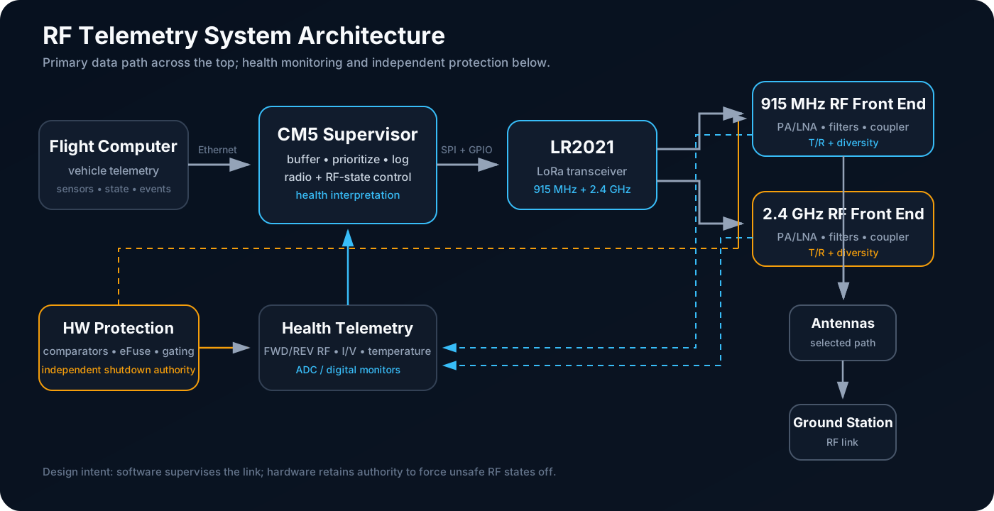
The RF measurement chain is there to answer two pretty basic questions: did I actually make RF power, and did the selected antenna path accept it without throwing a bunch of it back?
Measurement Flow
The directional coupler samples a small fraction of the forward and reflected traveling waves while leaving most of the RF power on the main transmission line. Those coupled RF samples are converted into low-bandwidth analog voltages by logarithmic detector circuitry and digitized for the CM5.
| Signal | What it indicates | Diagnostic value |
|---|---|---|
| Forward RF power | Energy leaving the PA toward the antenna | Confirms whether the TX chain is producing the expected output |
| Reflected RF power | Energy returning from the antenna/path | Indicates mismatch, damaged routing, or a poor antenna selection |
| PA current | Electrical load while transmitting | Helps distinguish normal RF load from electrical fault or abnormal operating point |
| PA temperature | Thermal stress | Supports power derating and independent thermal shutdown |
| Rail voltage | Supply integrity | Helps distinguish RF problems from power-tree faults |
Directional Coupler
I do not think of the coupler like an RF voltage divider. The useful part is that it gives me separate forward and reverse samples without stealing much power from the main line.
What the detector sees depends on the actual TX power, coupling factor, directivity, path loss, and mismatch, so there is no single magic conversion that is right everywhere. Final detector scaling therefore belongs in a measured calibration table rather than as one hard-coded theoretical conversion.
Log Detector and ADC
The ADL5519-class measurement approach converts RF input power into a DC voltage suitable for digitization. The ADC then exposes that measurement to the CM5 alongside current, voltage, and temperature channels.
A useful calibration record should include:
- Applied RF power at a calibrated reference plane
- Measured forward-detector voltage
- Measured reverse-detector voltage
- ADC code and reference voltage
- Frequency band
- Temperature
- Coupler path and antenna-switch state
What Limits VSWR Accuracy
Until I calibrate the whole chain properly, I trust it more as a 'something got significantly worse' detector than as a precision VSWR instrument.
Fault Interpretation
| Forward power | Reflected power | Likely interpretation |
|---|---|---|
| Low | Low | Radio/PA may not be transmitting, or TX path is disabled |
| Normal | Low | RF chain appears healthy and antenna match is likely acceptable |
| Normal | High | Antenna/path mismatch or damaged/disconnected RF path |
| High/abnormal | High | Possible calibration issue, switching fault, severe mismatch, or unexpected PA operating point |
I treat these as clues, not automatic conclusions. Software should combine RF power with switch state, commanded TX power, current, temperature, and fault inputs before changing antenna paths or disabling a PA.
Calibration / Validation Evidence
The portfolio should only promote this chain from design intent to measured performance after it includes:
- Detector transfer curves at both RF bands.
- Forward/reverse channel calibration using known RF power.
- Known mismatch tests using calibrated loads or an impedance tuner.
- Comparison against an external power meter or spectrum analyzer.
- Repeatability versus temperature and antenna-switch path.
- A documented uncertainty budget for any published VSWR or return-loss number.