Architecture
System electrical architecture
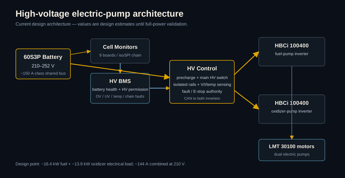
How the battery, BMS permission, precharge/main switching, dual inverters, and shared HV bus fit together.
~30 kW dual electric-pump power and control architecture with precharge, isolated power, sensing, and inverter CAN
Responsible Engineer
Project notes
Schematics, layout, bring-up, bugs, and the decisions behind the hardware.
The reasoning, bring-up, bugs, and test results behind the board.
Project overview
210–252 V
HV Bus
~30 kW
System Power
~144 A
Worst-Case Current
2× HBCi
Motor Drives
The high-voltage electrical system I am designing for two electric propellant pumps. I own the overall architecture and the HV Control/inverter integration: precharge, main switching, isolated local power, pack/bus sensing, fault authority, and CAN to the two motor drives.
Still in design. Nothing here is being presented as tested HV hardware yet; the power/current numbers, part choices, and precharge values are design-state values until staged testing happens.
Hardware & test evidence
Architecture
How the battery, BMS permission, precharge/main switching, dual inverters, and shared HV bus fit together.
Test history
Current architecture
Designed
I moved away from a custom ~30 kW inverter so the team can spend its effort on the battery, precharge, HV switching, sensing, CAN, and system-level fault handling.