Measured
5 V efficiency sweep
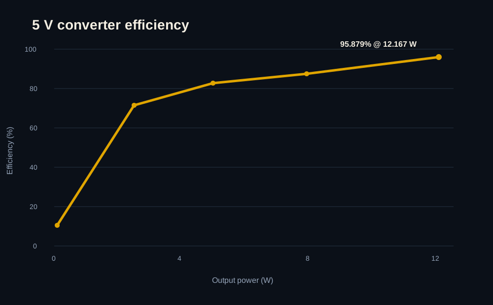
Measured 5 V converter efficiency across the board-load range, peaking at 95.879% at 12.167 W output.
Central flight-compute and black-box avionics board for sensing, storage, telemetry, and recovery coordination
Test Engineer
Browse the exported schematic and design sheets.
Look through the copper layers and routing.
Spin around the board model in 3D.
The reasoning, bring-up, bugs, and test results behind the board.
Project overview
95.9%
Peak 5 V Efficiency
0.1–12.5 W
5 V Load Range
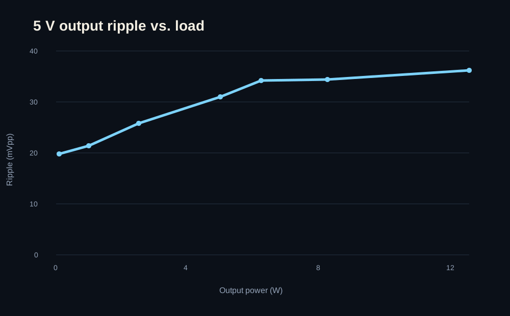
19.8–36.2 mVpp
Measured Ripple
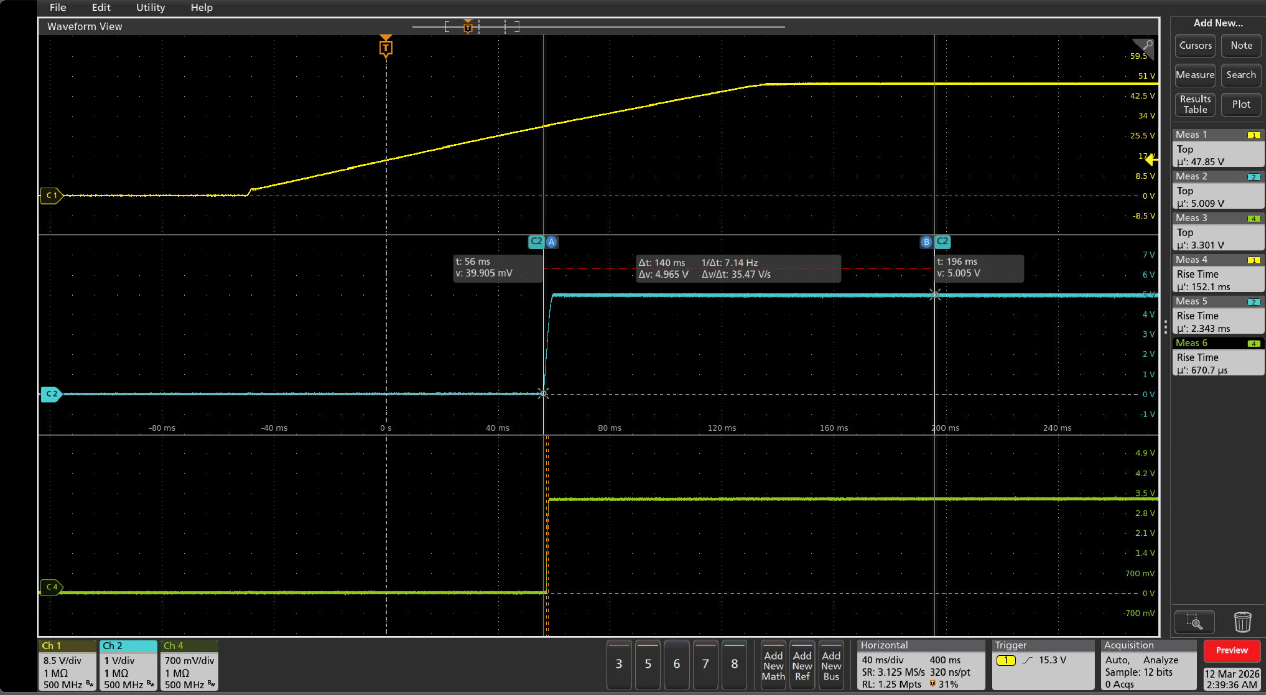
29.84 V VBUS
Rail Start
The main compute and data-recording board in the flight stack. I helped review parts of the design, then owned the bring-up side: power characterization, processor/sensor/interface checks, debugging, and keeping the board usable through subsystem and vehicle integration.
I did not design the whole Flight Computer. My ownership here is the bring-up, test, debugging, and system-validation work, so the page is written from that angle.
Hardware & test evidence
Measured
Measured 5 V converter efficiency across the board-load range, peaking at 95.879% at 12.167 W output.
Measured
Measured 5 V regulation and output ripple from 0.1 W through 12.5 W load.
Hardware
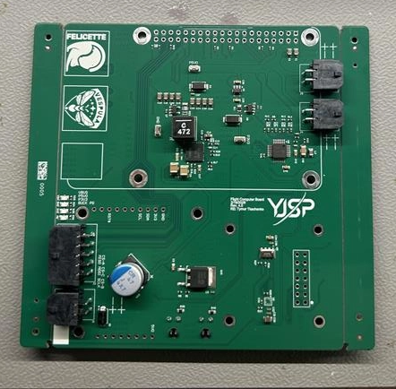
The Rev 4 Flight Computer I used for rail characterization, interface checks, and bring-up.
Integration
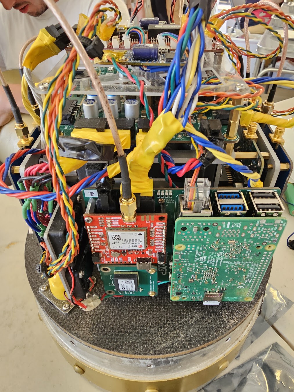
Flight Computer running as part of the larger avionics stack during integration.
Test history
Measure the 5 V converter across the load range I actually cared about on the board.
These are measurements only; I am not implying a separate pass/fail ripple limit here.
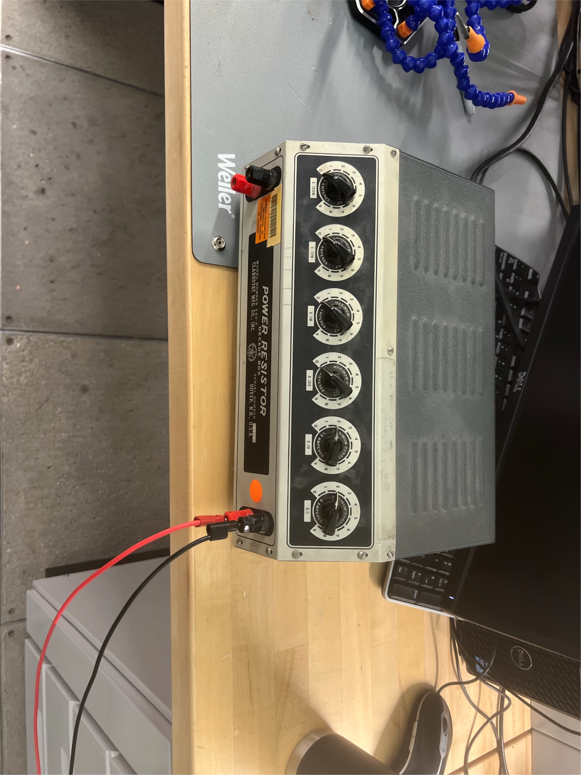
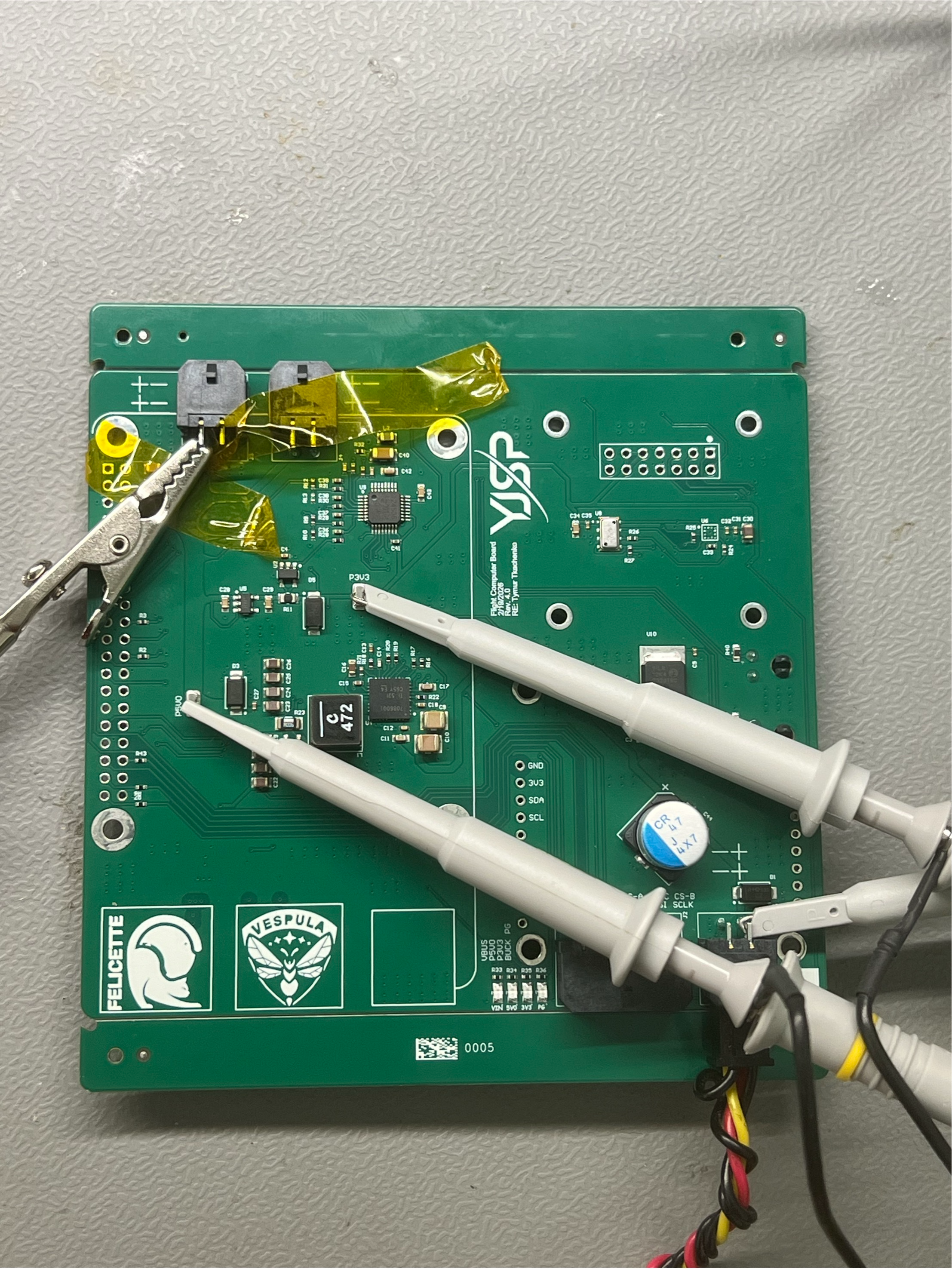
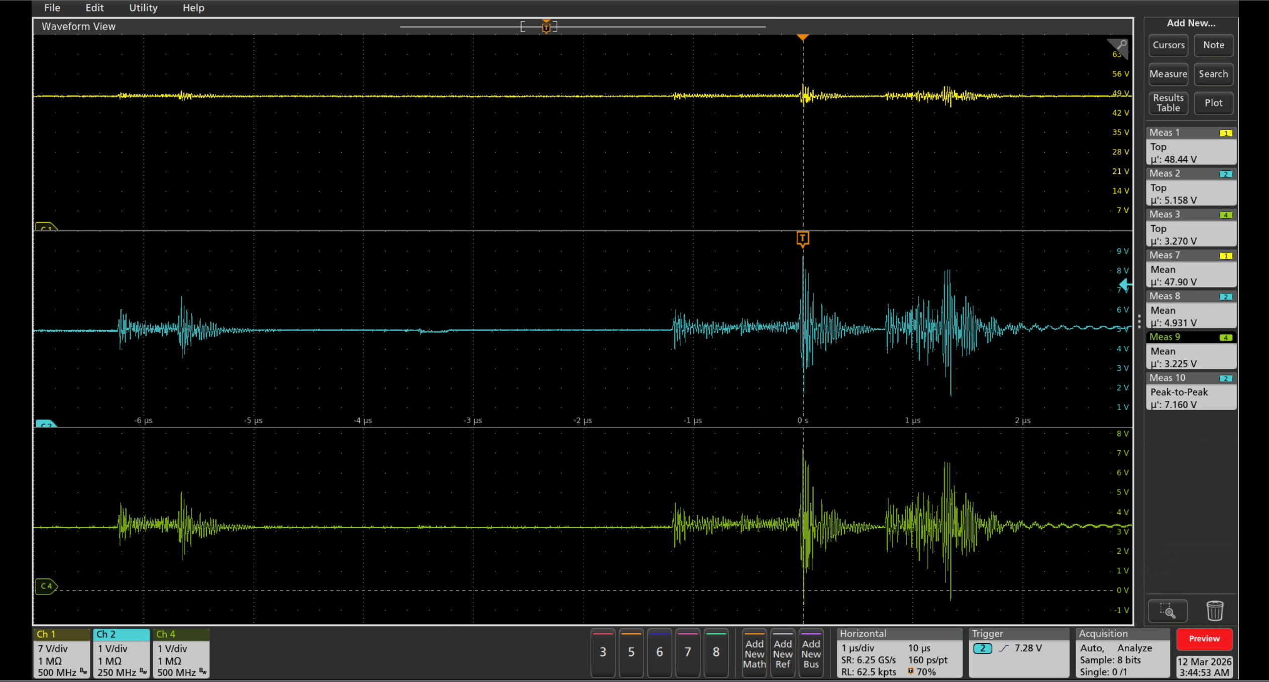
Watch startup and see how the 5 V rail handles a large load jump.
The attached scope captures are the actual rail startup and load-step measurements.
Rev 4 bring-up
Validated
Completed dead-board checks, rail sequencing, converter characterization, processor/sensor/interface checkout, and integrated board operation.